
Product images are for informational purposes only and may vary slightly depending on the batch and supplier. Product specifications and prices may be subject to change without notice. We do our best to provide accurate and complete product specifications, but they may not be completely accurate. If you encounter any such situation, please let us know.
The product is intended for specialists and requires qualified and authorized personnel. The product does not include assembly/use instructions . Putting the product into operation by unqualified persons leads to the loss of the warranty according to the Terms and Conditions on the site.
The specified technical parameters (current, power, etc.) represent maximum allowable values under ideal operating conditions. For safe use and optimal lifespan, it is recommended to operate the product continuously at no more than 50% of the specified maximum values.
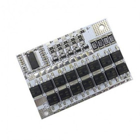
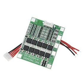
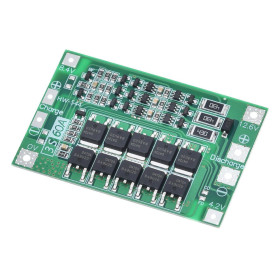
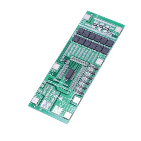
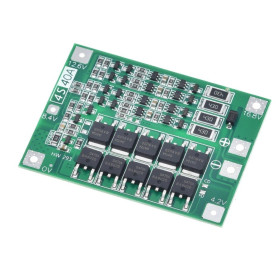
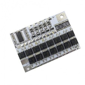
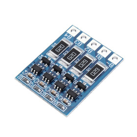
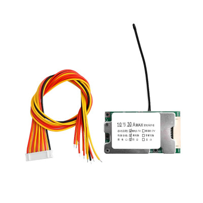
BMS module, 10S, 36V, 30A, with balancing, with heatsink, with thermistor
Protects and manages 10S 36V Li-ion packs for applications up to 1000W, ensuring stable charging and discharging. Offers cell balancing for better autonomy and lifespan, overcharge, overdischarge, overcurrent and short circuit protections, includes heat sink for heat dissipation and thermistor for temperature monitoring.
Shipping by Thursday 22 October
Buying this product earns you Ft289.80 in loyalty points.

International fast shipping within EU. Free Shipping for orders above 100 EUR in most EU countries.

We ship from our stock within 24H

You earn points with every order, worth 5%.
The 10S BMS protection module, 36V, 30A, with balancing, heatsink, and thermistor is an electronic board designed to manage and protect Li-ion or LiPo battery packs made of 10 cells connected in series (10S), such as 18650 cells or equivalent. The board is installed between the cell pack, charger, and load, automatically interrupts charging or discharging when dangerous voltages appear on any cell, and balances the voltages between cells during charging. It is suitable for electric bikes and scooters, tools, portable speakers, battery storage systems, and any project powered by a 10S pack with up to 1000 W.
The board provides overcharge protection at 4.25 V per cell, overdischarge protection at 2.6 V per cell, overcurrent and output short-circuit protection, and an NTC thermistor attached to the board adds overtemperature protection when placed in direct contact with the battery pack. The maximum accepted charging current is 10 A, continuous discharge supported is up to 25 A, and in short peaks the board tolerates up to 30 - 40 A, at a nominal voltage of 36 V. The balancing function activates above 4.1 V per cell and uses a current below 100 mA, enough to correct small differences between cells, but not to compensate for worn cells or cells with different capacities.
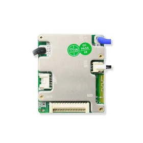
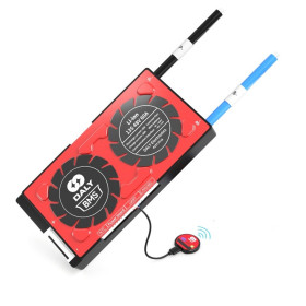
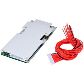
Among the main features are the heatsink mounted on the power transistors, the 11-wire balance connector (noted in the text as B0 - B10), the B+ and B- pins for the battery pack, the separate P- and C- pins for the discharge output and charging input respectively, and the NTC thermistor for measuring pack temperature, while the control circuit is powered directly from the connected battery pack, without a separate power supply.
Specifications:
Operating voltage: 36 V (10S)
Maximum operating current: 30 A, in short peaks up to 40 A
Maximum power: 1000 W
Charging voltage: 42 VDC
Charging current: 10 A
Maximum continuous current: 25 A
Overdischarge protection voltage: 2.6 V per cell
Overcharge protection voltage: 4.25 V per cell
Balance start threshold: above 4.1 V per cell, current below 100 mA
Temperature protection: Yes, via NTC thermistor mounted on the board
Compatible battery type: Li-ion / LiPo 18650 or equivalent, 4.2 V per cell
Dimensions: 64 x 35 x 9 mm
Pinout:
| Connector | Pin | Function |
|---|---|---|
| Battery pack | B- | Overall negative of the 10S pack, together with the negative of the balance connector |
| Balance connector (11 wires) | B0 (black wire) | 0 V, same point as B- |
| Balance connector | B1 (red) | Approximately 4.2 V |
| Balance connector | B2 (yellow) | Approximately 8.4 V |
| Balance connector | B3 (red) | Approximately 12.6 V |
| Balance connector | B4 (yellow) | Approximately 16.8 V |
| Balance connector | B5 (red) | Approximately 21 V |
| Balance connector | B6 (yellow) | Approximately 25.2 V |
| Balance connector | B7 (red) | Approximately 29.4 V |
| Balance connector | B8 (yellow) | Approximately 33.6 V |
| Balance connector | B9 (red) | Approximately 37.8 V |
| Balance connector | B10 (yellow) | Approximately 42 V, same point as B+ |
| Discharge output | P- | Load negative |
| Charging input | C- | Charger negative |
| Battery pack | B+ | Overall positive, connected directly to the positive of the charger and the load |
Usage:
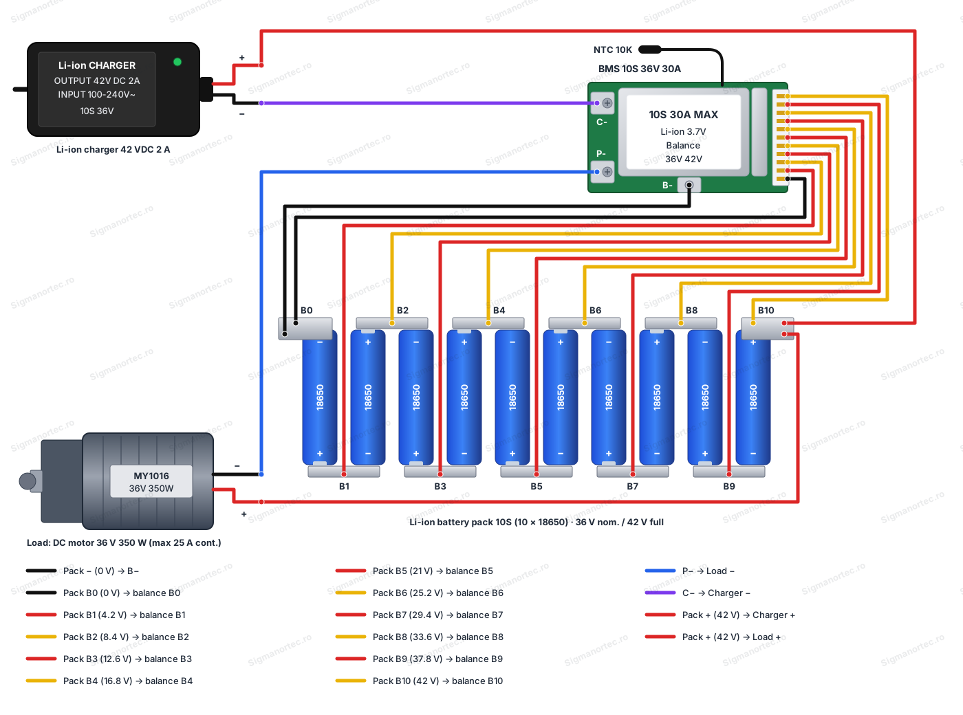
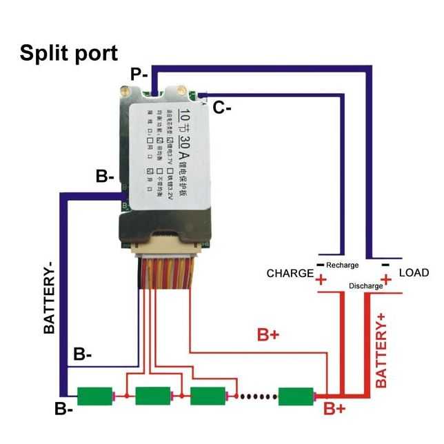
First connect the overall negative of the 10-cell pack to the B- pin on the board, together with the black B0 wire of the balance connector.
Then solder, in increasing voltage order, the balance connector wires from B1 to B10 to the successive points between the cells, alternating red and yellow colors, so that B1 reaches approximately 4.2 V, B2 8.4 V, B3 12.6 V and so on up to B10, which connects to the final positive of the pack, at approximately 42 V.
Measure each voltage with a multimeter before soldering the corresponding wire, to avoid reversing the order and damaging the board.
Insert the balance connector into the board connector only after all wires have been soldered and checked.
Connect the final positive of the pack B+ directly to the positive of the charging connector and the positive of the discharge connector, without passing through the board.
Connect the negative of the charging connector to the C- pin and the negative of the discharge connector, toward the load, to the P- pin.
Solder the NTC thermistor on the board in direct contact with one of the pack cells and secure it with adhesive tape or thermal tape, so that overtemperature protection works correctly.
Do not power the board without the cell pack connected correctly, and do not reverse polarity on the charging or discharging connectors.
Charge the pack only with a charger for 10S Li-ion, with a charging voltage of 42 VDC and a current of maximum 10 A, connected to the charging connector.
Before first use, balance the cells by individually charging them to the same level and connecting them in parallel for one to two days, especially if the cells come from different sources or have different levels of wear.
- Technology
- Lithium Ion
- sway
- Yes
- Nominal Current
- 30 A
- Number of cells
- 10S
- Input Voltage
- 36 V
Produs destinat utilizarii in proiecte electronice, automatizari, prototipare, educatie si cercetare.
Produsul trebuie utilizat numai conform specificatiilor tehnice mentionate in descriere si/sau in documentatia produsului.
Avertismente generale de siguranta:
Nu utilizati produsul la tensiuni, curenti sau temperaturi peste valorile specificate.
Montajul si conectarea trebuie realizate de persoane cu cunostinte tehnice minime in domeniul electric/electronic.
Evitati scurtcircuitele, inversarea polaritatii si conectarea gresita a alimentarii.
Nu lasati produsul alimentat nesupravegheat in timpul testelor.
Produsul nu este jucarie si nu este destinat copiilor.
Pentru modulele electronice, se recomanda utilizarea in carcase, panouri sau montaje protejate, dupa caz.
Identificare produs:
Denumirea produsului, codul/SKU-ul si caracteristicile tehnice sunt mentionate in pagina produsului si/sau pe eticheta ambalajului.
Producator / Importator / Distribuitor:
Sigmanortec S.R.L.
Calea Bucuresti nr. 9, Targu Jiu, Gorj, Romania
E-mail: [email protected]
Website: www.sigmanortec.ro
Persoana responsabila in UE:
Sigmanortec S.R.L.
Calea Bucuresti nr. 9, Targu Jiu, Gorj, Romania
E-mail: [email protected]
Documentatie si siguranta:
Pentru informatii suplimentare, fise tehnice, declaratii de conformitate sau instructiuni, ne puteti contacta la [email protected].
Reviews (2) - Review moderation

Firma f serioasa .
Acest bms se poate pune an paralel cu altele identiceamultumesc anticipat
The BMS Module 10S 36V 30A with balancing, heatsink and thermistor is a protection board for Li-ion or LiPo battery packs made of 10 cells connected in series, for example 10 18650 batteries. The board has no buttons, display or microcontroller of its own to program, it works as an automatic circuit installed between the cell pack, charger and load, so in this tutorial we don't use any development board, instead we show directly how to wire and how to put the module into operation.

How it works:
Each cell in a 10S pack has, in normal operation, a voltage between 2.6 V and 4.2 V, and the full pack varies between approximately 26 V (discharged) and 42 V (fully charged, 10 cells x 4.2 V). The board reads the voltage of each cell through the balance connector and stops charging when a cell reaches 4.25 V, stops discharging when a cell drops below 2.6 V and limits the current to 25 A continuous, respectively 30 A, with short peaks of up to 40 A.
The balancing function compares the cell voltages and, when one exceeds 4.1 V ahead of the others, it slightly drains its extra energy through a current under 100 mA, until all cells get close to the same level. This is a slow process, designed for small differences, and it cannot correct a worn cell or one with a capacity much different from the rest of the pack.
What you need:
- 1 x BMS Module 10S, 36V, 30A, with balancing, with heatsink, with thermistor
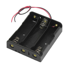
- 1 x 18650 4S Battery Holder
- 1 x Dual 18650 Li-ion Battery Charger
- 1 x DC Motor, 130, 3-6V
- 1 x Large gauge electrical wires for 25-30A
Connection:
The wiring is done between the 10 cell pack, the board's balance connector, the charger and the load, following exactly the order of the balance wires and the polarity of each connector.
| Product pin | Connects to | Role |
|---|---|---|
| B- | Overall minus of the 10S pack | Main ground of the board and pack |
| B0 - B10 (balance connector) | Successive points between cells, from 0 V to 42 V | Per-cell voltage monitoring and balancing |
| P- | Load minus (motor) | Discharge output |
| C- | Charger minus | Charging input |
| B+ (pack) | Charger plus and load plus | Overall plus, does not pass through the board |
Configuration:
The board has no buttons, display or potentiometer to adjust, because it is a fully automatic protection circuit, which starts working as soon as the cell pack is correctly connected to the balance connector and to the B-, B+, P- and C- pins.
The protection thresholds are factory set and cannot be changed, charging stop above 4.25 V per cell, discharge stop below 2.6 V per cell, and balancing starts automatically above 4.1 V per cell, with a current under 100 mA.
The only decision you make at assembly is how to wire the outputs, with C- and P- separate, as described in the table above, in order to be able to isolate the charging circuit from the discharging one.
Once the wires are soldered and the pack is assembled, the board remains in this configuration without needing any reset or reprogramming afterward.
Usage example:
A frequent example is powering a 36 V DC motor, for example a 350 W MY1016 motor, from a pack of 10 series connected 18650 cells protected by this module.
After the pack is assembled and the balance connector is soldered and plugged into the connector, connect the motor's minus to the board's P- pin, and the motor's plus directly to the pack's plus, together with the charging connector's plus.
For charging, connect a 42 VDC, 2 A charger to the charging connector, with the minus on the board's C- pin, charging stops automatically when the most charged cell reaches 4.25 V, and balancing kicks in above 4.1 V.
During motor operation, the board limits continuous discharge to approximately 25 A and stops the output if any cell drops below 2.6 V, protecting the pack from a deep discharge.
Common issues:
The load receives no current at all, the probable cause is that one of the cells has dropped below 2.6 V and the over-discharge protection has blocked the P- output, the solution is to charge the pack, the board automatically reactivates the output when the voltage returns above the threshold.
Charging stops before the pack reaches 42 V, the cause is usually a cell reaching 4.25 V ahead of the others due to a larger imbalance, the solution is to let charging continue longer so the balancing can equalize the cells or to manually balance the cells in parallel before assembly.
The board heats up visibly under heavy load, the cause is a sustained current above 25 - 30 A, over the board's continuous capacity, the solution is to reduce the load or add extra ventilation besides the existing heatsink.
The thermistor doesn't seem to trigger protection at high temperatures, the cause is a poor contact between the NTC and the cells, the solution is to redo the sensor's fixing with adhesive or thermally conductive tape directly on the casing of a cell from the middle of the pack.
A cell remains much different in voltage from the rest of the pack after several charges, the cause is a worn cell or one with a different capacity, and the balancing current under 100 mA cannot correct such a large difference, the solution is replacing that cell or reconditioning the pack.
The board trips randomly during charging or assembly, the frequent cause is a reversed order of the balance wires, the solution is to check with a multimeter the voltage of each connector pin relative to B-, the values should increase in steps of approximately 4.2 V.
Limitations and tips:
The board is rated for 30 A maximum and 25 A continuous, with short peaks of up to 40 A, it is not suitable for loads that constantly draw above these values.
Balancing with a current under 100 mA is slow and designed for small differences between cells, it does not replace the initial balancing of the cells before assembling the pack.
The board only works with Li-ion or LiPo cells charged to 4.2 V, it is not compatible with 3.2 V LiFePO4 cells.
For projects that need more advanced monitoring, for example each cell's voltage displayed separately or communication to a microcontroller, a BMS module with data output can be added alongside this basic protection module.