
Product images are for informational purposes only and may vary slightly depending on the batch and supplier. Product specifications and prices may be subject to change without notice. We do our best to provide accurate and complete product specifications, but they may not be completely accurate. If you encounter any such situation, please let us know.
The product is intended for specialists and requires qualified and authorized personnel. The product does not include assembly/use instructions . Putting the product into operation by unqualified persons leads to the loss of the warranty according to the Terms and Conditions on the site.
The specified technical parameters (current, power, etc.) represent maximum allowable values under ideal operating conditions. For safe use and optimal lifespan, it is recommended to operate the product continuously at no more than 50% of the specified maximum values.
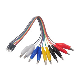
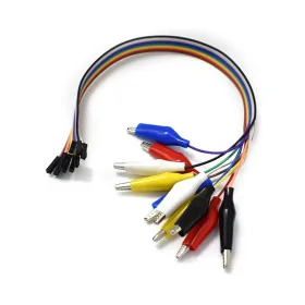
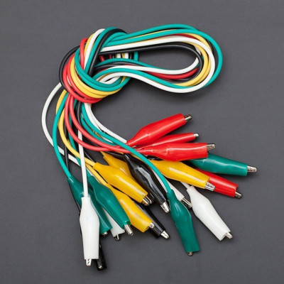
Alligator Clip Test Lead Kit, 10 pieces, 50 cm, clips at both ends, 5 colours
Ideal for quick testing and temporary connections in electronics, this set includes 10 leads of 50 cm with crocodile clips at both ends, ensuring a firm grip and stable contact. The different colours help to easily identify circuits, and the length offers flexibility on the workbench for measurements and prototyping.
Buying this product earns you 0.50 RON in loyalty points.

International fast shipping within EU. Free Shipping for orders above 100 EUR in most EU countries.

We ship from our stock within 24H

You earn points with every order, worth 5%.
The kit contains 10 test leads with crocodile (alligator) clips at both ends, intended for temporary solderless connections between power supplies, modules, measuring instruments and component terminals. They are suitable for the laboratory and workshop, for continuity tests, for temporary powering of a circuit and for checking a circuit before permanent soldering.
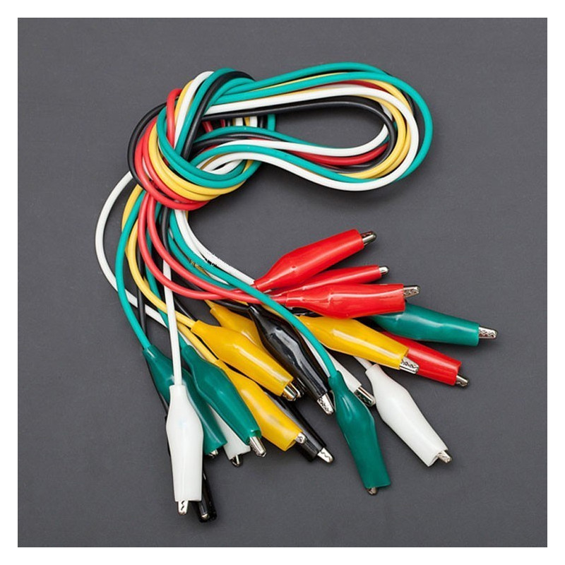
Each lead is 50 cm long and has two identical clips, so the connection has no polarity and can be used in either direction. The set includes 5 colours, 2 leads of each: red, black, yellow, green and white. The colours help to quickly recognise the connections in a circuit with several connection points.
The main features include the clips with serrated metal jaws, closed by a spring, the coloured insulated handles that protect the fingers and reduce the risk of accidental short circuits, the flexible cable and the 5 colours for marking connections. The set is a passive accessory, with no power supply of its own, intended for low-voltage circuits.
Specifications:
Product type: Test lead with crocodile clip at both ends
Quantity: 10 pieces
Cable length: 50 cm
Clips: Insulated, one at each end
Colours: Red, black, yellow, green, white (2 pieces of each)
Dimensions: 500 mm cable length
Usage:
Use the leads only at low voltages and do not connect them to the 220 VAC mains voltage.
Switch off the power to the circuit before attaching or removing the clips.
Squeeze the insulated handle of the clip to open the jaws, attach it to the terminal or binding post, then release the handle so that the spring closes the jaws firmly on the metal.
Attach the clip to the clean metal part of the terminal, not to the insulation, for a good contact.
Establish a colour convention and keep it in all circuits, for example red for positive supply, black for ground, yellow and green for signals, white for measurement points.
Check that the metal jaws, which extend beyond the handle, do not touch a neighbouring terminal or another clip.
Do not use the set for high currents, for example on car batteries or powerful motors. If a lead or a clip heats up, switch off the power immediately and switch to thicker leads.
After finishing the test, switch off the power before removing the leads from the circuit.
- Type
- Test lead with alligator clips at both ends
- Colour
- Red, black, yellow, green, white
- Cable length
- 50 cm
- Quantity
- 10 pieces
Produs destinat utilizarii in proiecte electronice, automatizari, prototipare, educatie si cercetare.
Produsul trebuie utilizat numai conform specificatiilor tehnice mentionate in descriere si/sau in documentatia produsului.
Avertismente generale de siguranta:
Nu utilizati produsul la tensiuni, curenti sau temperaturi peste valorile specificate.
Montajul si conectarea trebuie realizate de persoane cu cunostinte tehnice minime in domeniul electric/electronic.
Evitati scurtcircuitele, inversarea polaritatii si conectarea gresita a alimentarii.
Nu lasati produsul alimentat nesupravegheat in timpul testelor.
Produsul nu este jucarie si nu este destinat copiilor.
Pentru modulele electronice, se recomanda utilizarea in carcase, panouri sau montaje protejate, dupa caz.
Identificare produs:
Denumirea produsului, codul/SKU-ul si caracteristicile tehnice sunt mentionate in pagina produsului si/sau pe eticheta ambalajului.
Producator / Importator / Distribuitor:
Sigmanortec S.R.L.
Calea Bucuresti nr. 9, Targu Jiu, Gorj, Romania
E-mail: [email protected]
Website: www.sigmanortec.ro
Persoana responsabila in UE:
Sigmanortec S.R.L.
Calea Bucuresti nr. 9, Targu Jiu, Gorj, Romania
E-mail: [email protected]
Documentatie si siguranta:
Pentru informatii suplimentare, fise tehnice, declaratii de conformitate sau instructiuni, ne puteti contacta la [email protected].
Reviews (8) - Review moderation

Se pot folosi in proiecte mici, dar mansoanele ce izoleaza clestii sunt f. alunecoase. Trebuie o dexteritate aparte sa le poti prinde cu o singura mana si ... degete subtiri!
Probabil din cauza materialului din care este facut clestisorul nu permite curent mai mare de 1A. Sunt foarte buni pentru curenti mici dar la curenti mari au cadere de tensiune prea mare.
Calitate cam slaba...izolatia clestilor este alunecoasa... aluneca clestele de izolatie si devine dificil de folosit ...
Ok
OK Totul
The set of 10 crocodile clip cables, with a clip at each end, is a simple lab and workshop tool. Use it to quickly make temporary connections, without soldering, between a power supply, a module, a measuring instrument or the terminals of a component. This tutorial does not use any development board and does not need a program, because the set is a passive accessory. We put it into operation with a DC lab power supply.
In projects, the cables are used for continuity tests, for temporary powering of an assembly, for attaching multimeter probes to components with short or thick terminals, and for checking a circuit before soldering it permanently. The 5 colours in the set help you quickly recognise each connection.
How it works:
Each cable is a flexible conductor that electrically connects the two clips at its ends. The crocodile clip has two metal jaws with teeth, pressed towards each other by a spring. When you squeeze the insulated handle, the jaws open, and when you release it, the spring closes them on the gripped part. The electrical contact is made between the metal jaws and the part, and the coloured plastic handle protects your fingers and prevents accidental short circuits with nearby objects.
A cable behaves as a simple connection between two points, with no polarity, because both ends are identical. The 50 cm length is sufficient to reach from a bench power supply to an assembly placed on the table.
The cables are intended for low-voltage circuits. The higher the current through the cable, the hotter the wire and the clip contact become, so for high loads use thicker cables, made specifically for high currents.
Connection:
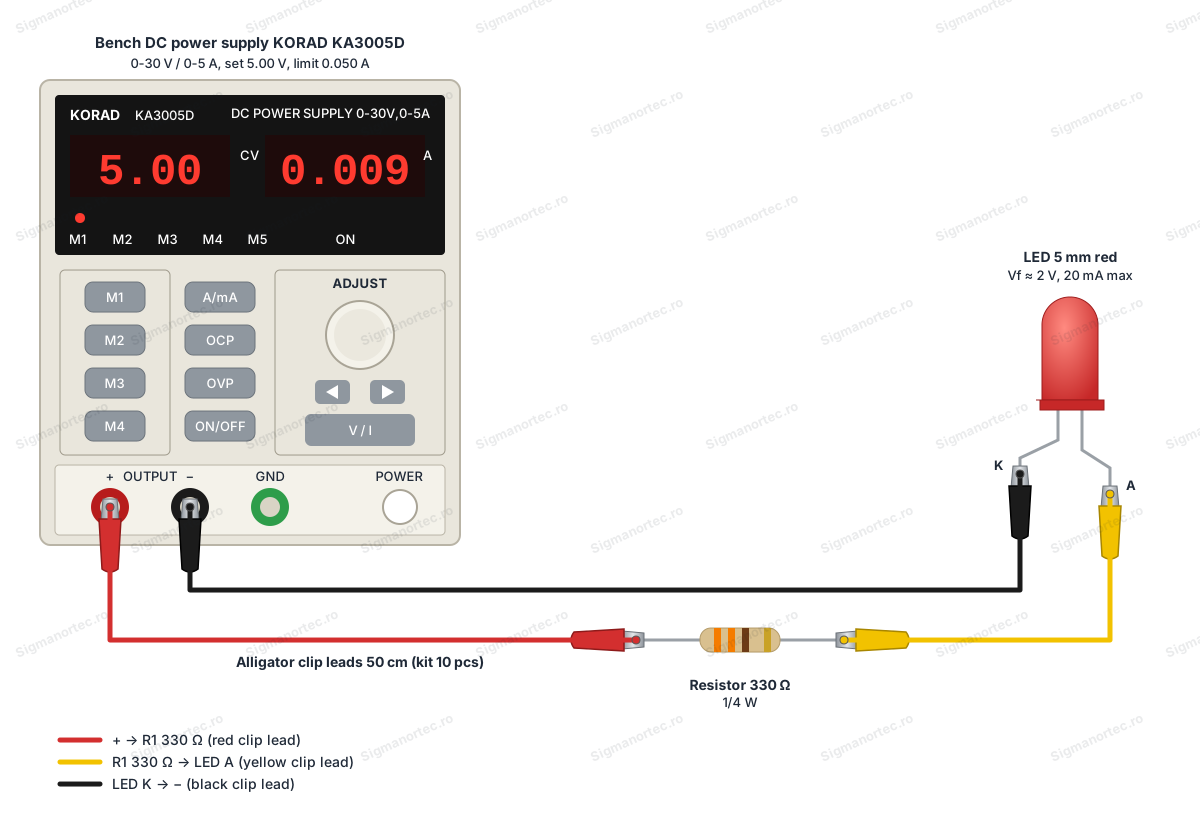
The set does not need power and has no pins. The table shows how the cables are used in the example of this tutorial, in which a lab power supply set to 5 V powers a red LED through a 330 ohm resistor. Use the set only at low voltages and not at the 220 VAC mains voltage.
| Product pin | Connects to | Role |
|---|---|---|
| Red cable, clip at the first end | The + (red) terminal of the lab power supply | Takes the positive 5 V supply |
| Red cable, clip at the second end | The first terminal of the 330 ohm resistor | Carries the positive supply to the resistor |
| Yellow cable, clip at the first end | The second terminal of the 330 ohm resistor | Takes the signal from the resistor |
| Yellow cable, clip at the second end | The LED anode (the longer leg) | Carries the current to the LED |
| Black cable, clip at the first end | The LED cathode (the shorter leg) | Returns the current from the LED |
| Black cable, clip at the second end | The - (black) terminal of the lab power supply | Circuit ground |
Attach the clips only to the + and - terminals of the power supply. The green GND (earth) terminal of the power supply is not used in this circuit.
Configuration:
The set has no buttons, jumpers or adjustments. The only thing you establish is the role of each colour in the assembly. Choose one rule and keep it in all projects, to avoid polarity mistakes.
| Colour | Recommended use |
|---|---|
| Red | Positive supply |
| Black | Ground (GND) |
| Yellow | Signal or data line |
| Green | Second signal or module output |
| White | Measuring point or auxiliary signal |
This assignment is only a working convention, not a requirement of the product. If you work in a team, write it on the workbench, so that everyone knows it.
Usage example:
This example powers a 5 mm red LED from a lab power supply set to 5 V, without a breadboard. You need a lab power supply (for example a KORAD KA3005D), a 5 mm red LED, a 330 ohm resistor (orange, orange, brown, gold bands) and three cables from the set: one red, one yellow and one black.
Turn off the power supply output and set the voltage to 5.00 V. Set the current limit to approximately 0.05 A, so that a possible short circuit does not damage the clips or the LED.
Attach one end of the red cable to the + terminal of the power supply and the other end to the first terminal of the resistor.
Attach one end of the yellow cable to the second terminal of the resistor and the other end to the LED anode, that is the longer leg. The yellow cable helps you tell apart the connection between the resistor and the LED.
Attach one end of the black cable to the LED cathode, that is the shorter leg, and the other end to the - terminal of the power supply.
Check that the jaws do not touch any other terminal and that no clip touches a neighbouring clip.
Turn on the power supply output. The LED should light up. The current through the LED is approximately (5 V - 2 V) / 330 ohm, that is about 9 mA, and the power supply display should show around 0.009 A. This value is below the usual maximum of 20 mA for a 5 mm LED, and the 1/4 W resistor dissipates only about 27 mW.
If the LED does not light up, turn off the power supply and reverse the LED terminals, because it was probably installed the wrong way round. After the test, turn off the power supply before removing the cables.
Common problems:
The circuit does not work even though all the clips seem attached. The usual cause is a weak contact, for example when the clip grips only the insulation or an oxidised part. Open the clip, clean the terminal and attach it again, with the jaws closed firmly on the metal.
A short circuit appears when you work near close pins. The cause is that the metal jaws extend beyond the handle and can touch the neighbouring terminal. Turn off the power and move the clips away from each other.
The clip slips off the terminal. The cause is usually the weight of the cable or a movement of the assembly. Position the cable so that it does not pull on the clip, and avoid clipping onto very thin or shiny parts.
The cable or the clip heats up. The cause is a current that is too high for the wire cross-section. Turn off the power immediately, let the cable cool down and switch to a thicker cable suited to the load current.
Multimeter measurements are unstable. The cause is an imperfect contact or a clip touching another metal object. Reattach the clip firmly and move it away from other conductive parts.
Limitations and tips:
The set is suitable for low-voltage assemblies and for short tests. Do not use it at the 220 VAC mains voltage and do not leave it unattended under load, because the clip jaws have a small contact surface. Do not use the cables for high currents, for example on car batteries or powerful motors.
The cables are not shielded. For fast or very sensitive signals, a long wire can pick up noise, and short connections give better results. For long-term work, where the connections will not change, switch to soldered wires or connectors.
With the set you can quickly build prototypes, test benches for modules with thick pins, and temporary connections between the power supply, the load and the measuring instruments.