
Product images are for informational purposes only and may vary slightly depending on the batch and supplier. Product specifications and prices may be subject to change without notice. We do our best to provide accurate and complete product specifications, but they may not be completely accurate. If you encounter any such situation, please let us know.
The product is intended for specialists and requires qualified and authorized personnel. The product does not include assembly/use instructions . Putting the product into operation by unqualified persons leads to the loss of the warranty according to the Terms and Conditions on the site.
The specified technical parameters (current, power, etc.) represent maximum allowable values under ideal operating conditions. For safe use and optimal lifespan, it is recommended to operate the product continuously at no more than 50% of the specified maximum values.
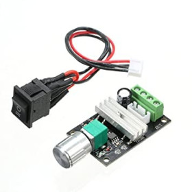
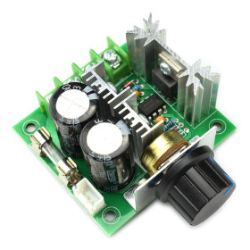
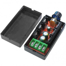
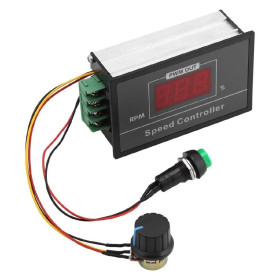
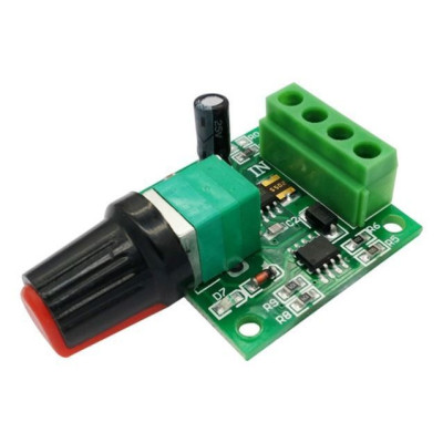
DC Motor Controller 1803BK, Adjustable PWM, 3-15V, 2A, 30W
Simple and precise motor speed control for DC motors, through PWM control with good efficiency and low losses. It works on a 3-15V supply and supports up to 2A, allows smooth speed adjustment with a potentiometer, and has a compact design that is easy to integrate into DIY projects, automation and light industrial applications.
Buying this product earns you 0.34 RON in loyalty points.

International fast shipping within EU. Free Shipping for orders above 100 EUR in most EU countries.

We ship from our stock within 24H

You earn points with every order, worth 5%.
The 1803BK PWM controller is a module for adjusting the speed of low-voltage DC motors. It can also be used to dim low-power resistive loads. The adjustment is made with a rotary knob potentiometer, and the module is suitable for fans, small pumps, RS-385 motors from toys and model cars, small workshop appliances or test benches.
The PWM signal is generated by an NE555 circuit, and the current to the motor is switched by a 9926A dual MOSFET transistor. The motor is not powered through a series resistor, but through pulses whose width is adjusted between 0 and 100 %. The average voltage at the motor equals the supply voltage multiplied by the duty cycle, so at the middle of the travel the motor receives half of the source voltage. The module supports a continuous current of 2 A and an output power of 30 W.
The main features include the potentiometer with integrated on/off switch, the green 4-position terminal block for power supply and motor, the input electrolytic capacitor, the 2 A resettable fuse and the D7 LED which indicates operation and follows the speed. The power supply is DC, in the 3 - 15 VDC range, from a source that can deliver at least the current required by the motor.
Specifications:
Supply voltage: 3 - 15 VDC
Maximum continuous current: 2 A
Maximum output power: 30 W
Adjustment method: PWM, duty cycle 0 - 100 %
PWM generator: NE555
Output transistor: 9926A dual MOSFET
Protection: 2 A resettable fuse
Control: Potentiometer with integrated on/off switch
Indicator: LED D7
Connection: Screw terminal block, 4 positions
Dimensions: 32 x 32 x 15 mm
Layout:
| Element | Function |
|---|---|
| Rotary knob potentiometer | Adjusts the duty cycle of the PWM signal between 0 and 100 %, thus the motor speed. Turned from the OFF position towards the opposite end, the speed increases, and turned back, the speed decreases. |
| Switch integrated in the potentiometer | Turns off the output when the knob is fully turned to the OFF end. A slight turn in the opposite direction turns the output on. |
| Screw terminal block, 4 positions | The pair next to the IN marking is the power input, and the other pair is the output to the motor. |
| NE555 circuit | Generates the PWM signal whose width is set by the potentiometer. |
| 9926A dual MOSFET transistor | Switches the current to the motor at the rhythm of the PWM signal. |
| 25 V electrolytic capacitor | The capacitor at the power input. |
| 2 A resettable fuse | Interrupts the circuit on overload and resets after cooling. |
| LED D7 | Lights up when the module is operating. Its brightness follows the duty cycle set by the potentiometer. |
| Mounting holes | Securing the board. |
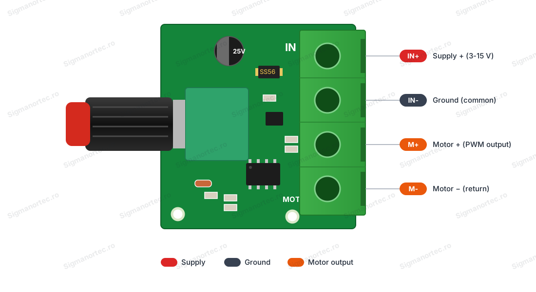
Pinout:
| Connector | Pin | Function |
|---|---|---|
| Terminal block, pair marked IN | IN+ | Power supply positive |
| Terminal block, pair marked IN | IN- | Power supply negative, common ground of the module and the motor |
| Terminal block, output pair | M+ | Output to the motor, voltage switched by PWM |
| Terminal block, output pair | M- | Output to the motor, current return path |
Usage:
Turn the knob fully to the OFF position before connecting the power supply, so that the motor does not start suddenly.
Connect the DC power supply to the terminal pair marked IN, and the motor or load to the output pair. The board does not have the polarities of the terminals marked, so check them with a multimeter or with the product wiring diagram before applying power.
Power the module from a DC source that can deliver at least 2 A and do not exceed 15 V. Respect the polarity, because there is no confirmed reverse polarity protection.
Switch off the power before any change to the connections. Tighten the terminal screws well and check that no copper strand touches the neighbouring terminal.
Turn the knob very slowly from OFF. At a certain angle the D7 LED lights up and the motor starts to rotate. Keep turning until the desired speed is reached. The adjustment is working when the motor speed and the brightness of the D7 LED increase as you turn.
To reduce the speed, turn the knob back. At the OFF end the output turns off.
To change the direction of rotation, switch off the power and reverse the two motor wires.
For additional protection, install a fuse of suitable value in series with the positive supply wire. Do not exceed the current of 2 A and the power of 30 W.
- Supply voltage
- 3-15 V DC
- Dimensions
- 32 x 32 x 15 mm
- Maximum current
- 2 A
- Connector type
- Screw terminal block, 4 positions
- Protections
- Resettable fuse 2 A
- Output power
- 30 W
- Integrated circuit
- NE555
- Control mode
- PWM, duty cycle 0-100%
Produs destinat utilizarii in proiecte electronice, automatizari, prototipare, educatie si cercetare.
Produsul trebuie utilizat numai conform specificatiilor tehnice mentionate in descriere si/sau in documentatia produsului.
Avertismente generale de siguranta:
Nu utilizati produsul la tensiuni, curenti sau temperaturi peste valorile specificate.
Montajul si conectarea trebuie realizate de persoane cu cunostinte tehnice minime in domeniul electric/electronic.
Evitati scurtcircuitele, inversarea polaritatii si conectarea gresita a alimentarii.
Nu lasati produsul alimentat nesupravegheat in timpul testelor.
Produsul nu este jucarie si nu este destinat copiilor.
Pentru modulele electronice, se recomanda utilizarea in carcase, panouri sau montaje protejate, dupa caz.
Identificare produs:
Denumirea produsului, codul/SKU-ul si caracteristicile tehnice sunt mentionate in pagina produsului si/sau pe eticheta ambalajului.
Producator / Importator / Distribuitor:
Sigmanortec S.R.L.
Calea Bucuresti nr. 9, Targu Jiu, Gorj, Romania
E-mail: [email protected]
Website: www.sigmanortec.ro
Persoana responsabila in UE:
Sigmanortec S.R.L.
Calea Bucuresti nr. 9, Targu Jiu, Gorj, Romania
E-mail: [email protected]
Documentatie si siguranta:
Pentru informatii suplimentare, fise tehnice, declaratii de conformitate sau instructiuni, ne puteti contacta la [email protected].
Reviews (6) - Review moderation

Functioneaza perfect.
Este un variator de tensiune, practic, isi face treaba cu brio. L-am testat pe modele de ventilatoare cu 2, 3 si 4 pini, evident, legat doar la bornele de + si - ale lor.
sunt produse ok,si cel mai important seriozitate
functioneaza pentru reglarea turatiei unui ventilator de server TA500dc (fir verde pt PWM la MOTOR- )
Bun
This tutorial uses the PWM 1803BK controller as a standalone module, without a development board and without a program. The module has its own PWM signal generation circuit, and its only adjustment is the potentiometer on the board. It is useful when you want to control the speed of a low-voltage DC motor, for example a fan, a small pump, an RS-385 motor from a car or a toy, or to dim a low-power resistive load.
Power it from a DC source, connect the motor to the output terminals and adjust the speed with the knob. It needs no other external components, because the board already has the input capacitor and the protection diode for inductive loads.

How it works:
The module does not reduce the voltage through a resistor. Instead, it switches the motor supply on and off very rapidly. The board has an NE555 circuit that generates the PWM (pulse width modulation) signal and a 9926A dual MOSFET transistor that switches the current to the motor. The wider the pulses, the more energy the motor receives and the faster it turns.
The ratio between the pulse duration and the duration of a complete period is called the duty cycle, and it is adjusted from the potentiometer between 0 and 100 %. The average voltage applied to the motor is calculated as follows: Vmotor = Vsupply x duty cycle. With a 12 V supply and a 50 % duty cycle, the motor receives 6 V on average. At 100 % it receives practically the full supply voltage.
The maximum output power is 30 W, and the maximum continuous current is 2 A. At 12 V, a motor that draws 2 A needs 12 V x 2 A = 24 W, so it is within the limit. The module has a 2 A resettable fuse, which cuts the circuit in case of overload and resets after it cools down.
The module cannot reverse the direction of rotation. The direction changes only by swapping the two motor wires, with the power switched off.
Connection:
Power the module with 12 VDC from a source of at least 2 A and never exceed 15 V. The screw terminals have 4 positions, and the board has the marking IN next to the end pair, which is intended for the power supply. The board does not have + and - signs marked on the terminals, so before applying power check the polarity with the wiring diagram from the seller or with a multimeter. To connect to a power source with a jack plug, use a 5.5 x 2.1 mm female jack adapter with screw terminals. No level converter is needed, because there are no logic signals.
| Product pin | Connect to | Role |
|---|---|---|
| IN+ | Positive of the 12 VDC source (the + terminal of the jack adapter) | Power supply of the module. |
| IN- | Negative of the 12 VDC source (the - terminal of the jack adapter) | Common ground of the module and the motor. |
| M+ | Red wire of the 12 VDC RS-385 motor | Output to the motor, voltage switched by PWM. |
| M- | Black wire of the 12 VDC RS-385 motor | Output to the motor, return path for the current. |
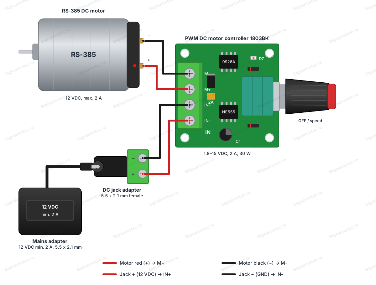
Switch off the power before making any changes to the connections. For additional protection you can fit a fuse in series with the positive supply wire. Do not reverse the polarity of the source, because there is no confirmed reverse polarity protection.
Buttons, adjustments and indicators:
| Element | What it does | How to use it |
|---|---|---|
| Potentiometer with rotary knob | Adjusts the duty cycle of the PWM signal between 0 and 100 %, therefore the motor speed. | Turn the knob from the OFF position towards the opposite end to increase the speed. Turn it back to decrease it. |
| Switch built into the potentiometer | Turns the output off when the knob is turned fully to the stop end. | Turn the knob all the way to the OFF position to stop. Turn it slightly in the opposite direction to start. |
| LED D7 | Shows that the module is powered and follows the motor speed. | It lights up when the module is operating. Its brightness follows the duty cycle set with the potentiometer. |
Starting position: turn the knob fully to the OFF position before connecting the source, so that the motor does not start suddenly.
Speed adjustment: after applying power, turn the knob very slowly from the OFF position. At a certain angle the LED D7 lights up and the motor starts to turn. Keep turning until you reach the desired speed. If you turn the knob back, the speed decreases, and at the stop end the motor stops.
How to see that the adjustment works: the motor speed changes smoothly as you turn the knob, and the brightness of LED D7 changes at the same time.
Configuration:
The module has no menu, programming buttons or memory. The only parameter is the duty cycle, set by the mechanical position of the potentiometer. The setting is kept when the power is switched off, because the knob stays in the position where you left it. When restarted, the module returns to exactly the same speed.
The table below shows the average voltage applied to the motor for several knob positions, with a 12 VDC supply. The values are indicative, because the exact position depends on the potentiometer.
| Knob position | Duty cycle | Average voltage at the motor |
|---|---|---|
| OFF (stop end) | 0 % | 0 V |
| One quarter of the travel | 25 % | 3 V |
| Half of the travel | 50 % | 6 V |
| Three quarters of the travel | 75 % | 9 V |
| Maximum end | 100 % | 12 V |
To change the direction of rotation, unplug the power supply, swap the wires at the M+ and M- terminals, and only then power up the module again.
Usage example:
The goal of the example is to adjust the speed of a 12 VDC RS-385 motor, which draws less than 2 A in operation, from a 12 VDC and 2 A mains power supply.
Step 1. Unplug the power supply. Connect the 5.5 x 2.1 mm jack adapter to the source. Connect the + terminal of the adapter to IN+ and the - terminal to IN-, after checking the polarity of the terminals with the wiring diagram from the seller or with a multimeter.
Step 2. Connect the red motor wire to M+ and the black wire to M-. Tighten the screws well and check that no copper strand comes out of the terminal and touches the neighboring terminal.
Step 3. Turn the knob fully to the OFF position. Plug the source into the mains. The motor must stay stopped.
Step 4. Turn the knob slowly. The LED D7 lights up, and the motor starts at a low speed. Turn to the middle of the travel, where the motor receives about 6 V on average, and observe how the speed increases and the LED D7 becomes brighter.
Step 5. Turn the knob to the maximum end for full speed, then back to the desired speed. To stop, turn the knob fully to the OFF position.
Step 6. If the motor turns in the opposite direction to the desired one, unplug the power supply, swap the motor wires at M+ and M-, and repeat the steps from Step 3.
Common problems:
The motor does not start and LED D7 stays off. The most likely cause is the knob left in the OFF position or the source connected with the wrong polarity. Turn the knob slightly from OFF in the opposite direction, then check the polarity with a multimeter and the connections to IN+ and IN-.
The motor starts only after a certain angle of the knob. This is normal, because at low duty cycles the average voltage is too low to overcome the friction of the motor. Keep turning the knob until the motor starts.
The motor stops suddenly or works intermittently. The 2 A resettable fuse has tripped because of an overload or a locked motor. Switch off the power, remove the cause, let the module cool down and put it back into operation.
The motor does not reach maximum speed or the LED goes out under heavy load. The source cannot deliver the required current and its voltage drops. Use a source of at least 2 A, with a voltage suitable for the motor.
The motor turns in the reverse direction. The module cannot reverse the direction. Switch off the power and swap the motor wires at the M+ and M- terminals.
The module heats up. This is normal at currents close to 2 A. Reduce the load or provide ventilation if the temperature becomes too high.
Limitations and tips:
The module accepts at most 15 V at the input, a continuous current of 2 A and a power of 30 W. It cannot reverse the direction of rotation and does not measure the speed, so the real speed depends on the load and the source voltage. The board does not have confirmed reverse polarity protection.
For stable adjustment, use a power supply suitable in voltage and current and wires of sufficient cross-section. You can fit a fuse in series with the positive supply wire. With the module you can build speed controllers for fans and small pumps, mechanisms for toys and model cars, or dimmers for low-power resistive loads.