
Product images are for informational purposes only and may vary slightly depending on the batch and supplier. Product specifications and prices may be subject to change without notice. We do our best to provide accurate and complete product specifications, but they may not be completely accurate. If you encounter any such situation, please let us know.
The product is intended for specialists and requires qualified and authorized personnel. The product does not include assembly/use instructions . Putting the product into operation by unqualified persons leads to the loss of the warranty according to the Terms and Conditions on the site.
The specified technical parameters (current, power, etc.) represent maximum allowable values under ideal operating conditions. For safe use and optimal lifespan, it is recommended to operate the product continuously at no more than 50% of the specified maximum values.
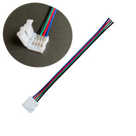
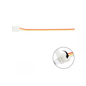
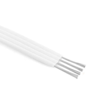
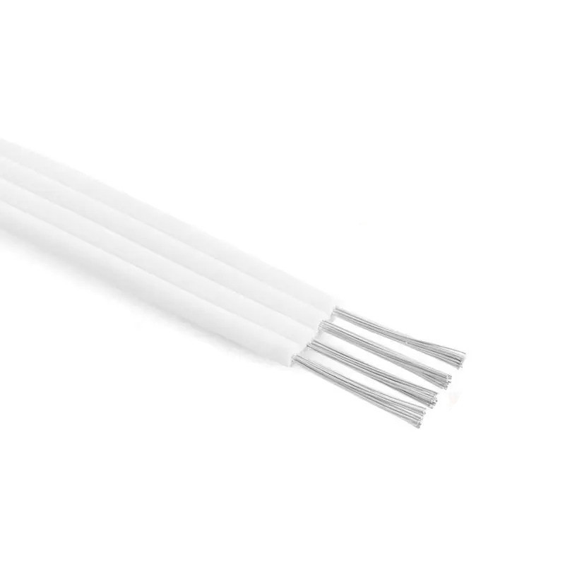
4-wire extension cable for RGB LED strip, 20 AWG, 1 meter
Extension cable with 4 wires of 20 AWG, tinned copper conductor and PVC insulation, for analog RGB LED strips and WS2811 or WS2812 addressable strips powered at 12V. The stripped and tinned ends allow soldering, terminal block connection, or crimping, while maintaining the order of the power and signal wires between the controller and the strip. It withstands 300 VDC and 80 °C, making it ideal for extending decorative lighting installations.
Shipping by Thursday 22 October
Buying this product earns you Ft36.92 in loyalty points.

International fast shipping within EU. Free Shipping for orders above 100 EUR in most EU countries.

We ship from our stock within 24H

You earn points with every order, worth 5%.
The 4-wire extension cable is used to increase the distance between the power source or RGB controller and the LED strip, keeping the power lines separate from the signal lines. It is used with 12V analog RGB LED strips, as well as with WS2811 and WS2812 addressable strips also powered at 12V, in decorative lighting installations, perimeter strips, luminous furniture, and projects where the strip must be placed away from the power source or controller.
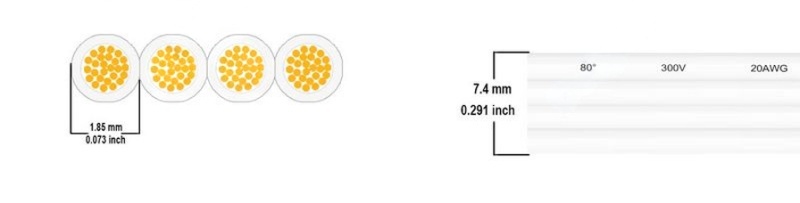
The 4 conductors are made of tinned copper with a 20 AWG cross-section, individually insulated in PVC and arranged side by side in a flat cable, easy to pull through channels or protective tubes. The insulation supports a rated voltage of 300 VDC and an operating temperature of up to 80 °C, values that comfortably cover the typical 12V supply of LED strips. The cable ends are stripped and tinned, ready for soldering, fastening in a screw terminal block, or crimping with connectors compatible with the connector on the strip or controller.
Among the main features are the 4 white wires, identical to each other, the tinned copper conductor with a 20 AWG cross-section, the thermally resistant PVC insulation, and the already stripped wire ends. The cable has no polarity marked on the insulation, so the power wire must be identified and marked by the user before connection; the actual power is carried through one of the 4 wires, while the other three carry the signals to the strip or controller.
The cable is compatible with analog RGB LED strips and with WS2811 and WS2812 addressable strips powered at 12V, making it suitable for extending the connection between them and RGB controllers, IR receivers, or power supplies, including in installations controlled from Arduino, ESP32, or other development boards through a dedicated controller or driver.
Specifications:
Rated voltage: 300 VDC
Type: extension cable
Number of wires: 4
Conductor cross-section: 20 AWG
Insulation color: white
Conductor: tinned copper
Insulation: PVC
Maximum operating temperature: 80 °C
Compatibility: WS2812, WS2811 LED strips and analog RGB strips at 12V
Use:
Identify the end toward the power source or controller and the end toward the LED strip, then mark with adhesive tape or a marker the wire that will carry +12V, so you do not confuse the wires with each other, since all 4 wires have the same white color.
Check with a multimeter, in continuity mode, that each wire is uninterrupted from one end to the other before making any permanent connection.
Connect the cable ends by soldering, by screw terminal block, or by crimping with compatible connectors, respecting the same wire order at both ends, so that the +12V, G, R, and B wires correspond between the controller or power supply and the strip.
For 4-wire RGB strips, verify the correspondence of the R, G, and B color channels at both ends, because reversing them changes the colors displayed by the strip compared with those commanded by the controller.
Do not power the strip or controller before finishing all connections and insulating each joint with heat-shrink tubing, to avoid short circuits between adjacent wires.
Power the installation only after checking the polarity and wire order, respecting the 12V voltage used by the strip and the controller.
Keep the cable as short as possible when the transported current is high, because with 20 AWG the voltage drop increases with length and current, and over long distances the strip brightness may decrease.
Do not exceed the rated voltage of 300 VDC and the maximum operating temperature of 80 °C of the insulation; the cable is intended for low-voltage 12V circuits of LED strips.
Dimension diagram:
- Connector type
- JST
- Number of pins
- 4
- Wire gauge (AWG)
- 20 AWG
Produs destinat utilizarii in proiecte electronice, automatizari, prototipare, educatie si cercetare.
Produsul trebuie utilizat numai conform specificatiilor tehnice mentionate in descriere si/sau in documentatia produsului.
Avertismente generale de siguranta:
Nu utilizati produsul la tensiuni, curenti sau temperaturi peste valorile specificate.
Montajul si conectarea trebuie realizate de persoane cu cunostinte tehnice minime in domeniul electric/electronic.
Evitati scurtcircuitele, inversarea polaritatii si conectarea gresita a alimentarii.
Nu lasati produsul alimentat nesupravegheat in timpul testelor.
Produsul nu este jucarie si nu este destinat copiilor.
Pentru modulele electronice, se recomanda utilizarea in carcase, panouri sau montaje protejate, dupa caz.
Identificare produs:
Denumirea produsului, codul/SKU-ul si caracteristicile tehnice sunt mentionate in pagina produsului si/sau pe eticheta ambalajului.
Producator / Importator / Distribuitor:
Sigmanortec S.R.L.
Calea Bucuresti nr. 9, Targu Jiu, Gorj, Romania
E-mail: [email protected]
Website: www.sigmanortec.ro
Persoana responsabila in UE:
Sigmanortec S.R.L.
Calea Bucuresti nr. 9, Targu Jiu, Gorj, Romania
E-mail: [email protected]
Documentatie si siguranta:
Pentru informatii suplimentare, fise tehnice, declaratii de conformitate sau instructiuni, ne puteti contacta la [email protected].
This tutorial shows how to use the 4-wire extension cable to extend the connection between a 12V RGB controller and an analog RGB LED strip, without any development board and without code, being just a simple power and signal extender.
The setup below is useful when the controller and power supply are mounted in one place, and the LED strip needs to reach a few meters away, for example behind furniture, on a false ceiling or along a wall.
How it works:
An analog RGB LED strip has a single common 12V plus wire and a separate wire for each color, R, G and B, each color wire being actually connected to ground through the inside of the controller, proportionally, through PWM modulation, to obtain the desired color and brightness. The extension cable does not modify the signal, but only transports the same 4 lines over a greater distance between the controller and the strip.
The 20 AWG conductor has a resistance of approximately 33 mOhm per meter. At a 2 m extension, the total length traveled by the current on the way there and back is 4 m, and at a current of 2 A the resulting voltage drop is approximately 33 mOhm per meter multiplied by 4 m and by 2 A, that is approximately 0.27 V, a small enough value to not visibly affect the strip's operation.
A 5050 RGB strip with 60 LEDs per meter consumes, on average, approximately 14.4 W per meter, that is approximately 1.2 A per meter at 12V. A 12V 2A adapter can safely power approximately 1.5 m of strip, and for a 5 m strip you need a source of at least 6 A or power from multiple points.
What you need:
- 1 x LED Wire JST Connector Extension 4Pin 20AWG Multicolor
- 1 x 12V 2A power adapter
- 1 x 12V RGB IR controller with 24 buttons
- 1 x Addressable LED strip, RGB, WS2812, 60led/m, 10cm, White
Connection:
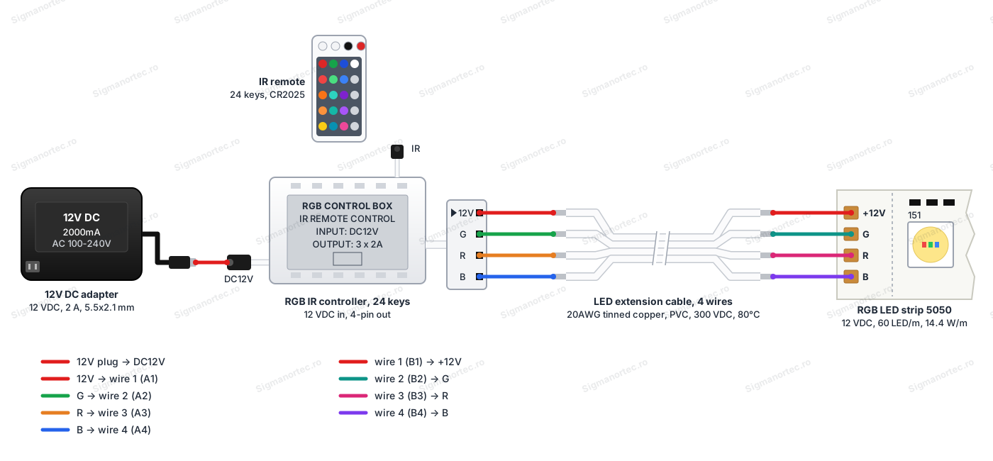
First power the RGB controller from the 12V 2A adapter through the DC connector of the controller, then use the extension cable to connect the 4-wire output of the controller to the input of the LED strip, keeping the same order of wires at both ends. All 4 wires of the cable are white and identical to each other, so mark the 12V plus wire at both ends before connecting anything, to avoid reversing the power with a color channel.
| Product pin | Connects to | Role |
|---|---|---|
| A1 | Controller 12V output | 12V plus power |
| A2 | Controller G output | Green channel signal |
| A3 | Controller R output | Red channel signal |
| A4 | Controller B output | Blue channel signal |
| B1 | LED strip plus 12V input | 12V plus power |
| B2 | LED strip G input | Green channel signal |
| B3 | LED strip R input | Red channel signal |
| B4 | LED strip B input | Blue channel signal |
Configuration:
Cut the cable ends to the required length and strip the wires again if you shortened them, keeping a few millimeters of tinned copper free for soldering or for clamping in a terminal block.
Mark the wire chosen for 12V plus with colored adhesive tape or with a marker, at both ends of the cable, because the white insulation does not otherwise allow distinguishing the wires from each other.
Choose the joining method suitable for the equipment you have, soldering with solder and terminal, clamping in a terminal block with screws or crimping with connectors compatible with the strip and controller connectors.
Test the continuity of each wire with a multimeter before powering, to be sure there are no breaks or short circuits between wires along the cable length.
Once soldered or crimped, the joints remain fixed, so the marking made on the wire remains valid throughout the installation's service life, with no other settings to keep.
Example of use:
In a typical installation, the 24-button RGB controller and the 12V 2A adapter sit hidden in a connection box, and the 5050 RGB LED strip is mounted 2 m away, on a furniture profile. The extension cable is installed between the controller output and the end of the strip, with the 12V plus, G, R and B wire in the same order at both ends. After powering, pressing the color buttons on the IR remote changes the color of the entire strip, and the brightness buttons adjust the intensity, just as if the strip were connected directly to the controller, without the extension cable.
Frequent issues:
The LED strip does not start at all, although the controller has the operating LED on, a situation in which the most frequent cause is a break on the 12V plus wire in the extension cable or a poor joint, easily verified with a continuity test.
The colors displayed by the strip do not match those selected on the remote, a case in which the R, G or B wires were reversed between each other at one of the cable ends, and the remedy consists in reopening the joints and redoing them in the correct order.
The strip lights up weakly or has a slightly yellowish color compared to normal at the far end, a sign that on a long extension the voltage drop on the cable has become too large, a situation in which a shorter cable is recommended or feeding the strip from both ends.
The joints heat up noticeably during operation, which indicates either a weak contact made during soldering or crimping, or a current too large for the 20 AWG section on that wire, in which case the joint must be redone or the load reduced.
Two wires appear to be short-circuited to each other, a frequent situation when the tinned copper wires remain uninsulated and unshielded after joining, remedied by covering each joint with individual heat-shrink tubing.
Limitations and tips:
The cable is a simple 4-wire conductor of 20 AWG, without polarity marked on the insulation and without a pre-assembled connector, so the precision of the assembly depends entirely on the correct marking of the wires and the quality of the joints made by the user.
The 20 AWG section is suitable for the usual currents of a single RGB strip segment, but on long extensions or on large loads it is recommended to limit the current on the wire and feed the strip from both ends, to reduce voltage drop and wire heating.
With the same cable you can also extend addressable WS2811 or WS2812 strips powered at 12V, using the 12V plus, GND and DIN wires instead of the R, G and B lines, as long as the DIN signal direction is respected from the controller to the strip.