
Product images are for informational purposes only and may vary slightly depending on the batch and supplier. Product specifications and prices may be subject to change without notice. We do our best to provide accurate and complete product specifications, but they may not be completely accurate. If you encounter any such situation, please let us know.
The product is intended for specialists and requires qualified and authorized personnel. The product does not include assembly/use instructions . Putting the product into operation by unqualified persons leads to the loss of the warranty according to the Terms and Conditions on the site.
The specified technical parameters (current, power, etc.) represent maximum allowable values under ideal operating conditions. For safe use and optimal lifespan, it is recommended to operate the product continuously at no more than 50% of the specified maximum values.
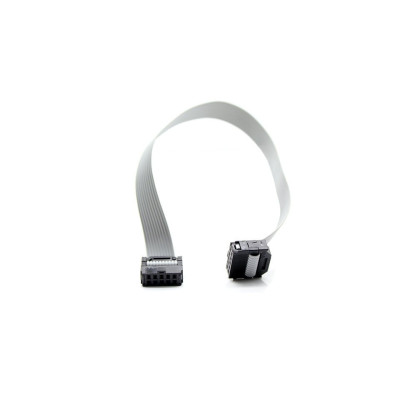
Ribbon cable, 10 pins, 2X5, 20cm
10-pin 2x5 ribbon cable, ideal for connecting LCD modules to the Ramps 1.4 shield in 3D printing and electronics projects. It is 20 cm long for flexible mounting, has connectors at both ends for quick installation, a standard pitch for broad compatibility, and a flat construction that reduces cable clutter.
Shipping by Wednesday 11 November
Buying this product earns you 0.41 RON in loyalty points.

International fast shipping within EU. Free Shipping for orders above 100 EUR in most EU countries.

We ship from our stock within 24H

You earn points with every order, worth 5%.
The 10-pin ribbon cable with 2X5 IDC connectors at both ends connects two 2-row sockets with 5 positions each, without soldering and without adapters. The 10 conductors are laid parallel in a flat band, and each pin at one end reaches the pin with the same number at the other end. It is suitable for connecting LCD displays, controllers with two EXP1 and EXP2 sockets, modules and control boards that use 2X5 connectors, in 3D printers, laboratory equipment and electronics projects.
The cable is 20 cm long, enough for compact assemblies in which the two sockets are close to each other. The connection is one-to-one, without crossovers and without active components, so the cable carries the signals and power supplied by the source board unchanged. The pin pitch is 2.54 mm, the one also used by common 2X5 sockets.
Main features include IDC connectors with 10 positions mounted on both ends, the flat band with 10 conductors that takes up little space and is easy to arrange in enclosures, as well as connector housings with an orientation key, which fit into the socket in only one position. The cable does not need its own power supply.
Specifications:
Type: Flat ribbon cable with IDC connectors
Number of conductors: 10
Connectors: IDC 2 x 5 pins, at both ends
Pin pitch: 2.54 mm
Connection: Pin to pin, 1 to 1, no crossovers
Length: 20 cm
Usage:
Turn off the power to both boards before inserting or removing the connectors, because the power pins and signal pins are adjacent and a wrong contact on a powered board can damage the circuits.
Identify the pin 1 marking on each socket, usually a triangle, the number 1 or a guide notch, then orient the connectors so that the same pin 1 is at both ends of the connection.
Insert the connectors fully, straight and without force. If a connector does not go in easily, check the orientation and do not force it, as the socket pins may bend.
If the equipment has two 2X5 sockets, such as EXP1 and EXP2, use one cable for each socket and connect EXP1 to EXP1 and EXP2 to EXP2.
Leave the cable with a slight loop, avoid tight bends near the connector and do not clamp it between moving parts.
The cable does not change the voltage or amplify the signal, so check in the boards' documentation that the logic levels and power supply on the two sockets match.
- Type
- Flat ribbon cable with IDC connectors
- Length
- 20 cm
- Connector type
- IDC 2 x 5 pins
- Number of wires
- 10
- Pin pitch
- 2.54 mm
Produs destinat utilizarii in proiecte electronice, automatizari, prototipare, educatie si cercetare.
Produsul trebuie utilizat numai conform specificatiilor tehnice mentionate in descriere si/sau in documentatia produsului.
Avertismente generale de siguranta:
Nu utilizati produsul la tensiuni, curenti sau temperaturi peste valorile specificate.
Montajul si conectarea trebuie realizate de persoane cu cunostinte tehnice minime in domeniul electric/electronic.
Evitati scurtcircuitele, inversarea polaritatii si conectarea gresita a alimentarii.
Nu lasati produsul alimentat nesupravegheat in timpul testelor.
Produsul nu este jucarie si nu este destinat copiilor.
Pentru modulele electronice, se recomanda utilizarea in carcase, panouri sau montaje protejate, dupa caz.
Identificare produs:
Denumirea produsului, codul/SKU-ul si caracteristicile tehnice sunt mentionate in pagina produsului si/sau pe eticheta ambalajului.
Producator / Importator / Distribuitor:
Sigmanortec S.R.L.
Calea Bucuresti nr. 9, Targu Jiu, Gorj, Romania
E-mail: [email protected]
Website: www.sigmanortec.ro
Persoana responsabila in UE:
Sigmanortec S.R.L.
Calea Bucuresti nr. 9, Targu Jiu, Gorj, Romania
E-mail: [email protected]
Documentatie si siguranta:
Pentru informatii suplimentare, fise tehnice, declaratii de conformitate sau instructiuni, ne puteti contacta la [email protected].
This tutorial uses the 10-pin ribbon cable, 2X5, 20 cm long, as a connecting accessory, without a development board and without a program. The cable has a connector with 2 rows of 5 positions at each end (IDC type), and the 10 parallel flat wires keep the pin order from one end to the other.
It is used to connect two boards or modules that have 2X5 sockets, for example an LCD controller to a 3D printer control board.

How it works:
The cable consists of 10 insulated conductors, placed side by side in a flat ribbon. At each end, the connector is pressed onto the ribbon and each contact pierces the insulation of a single conductor. For this reason, pin 1 at one end is directly connected to pin 1 at the other end, pin 2 to pin 2, and so on up to pin 10. The connection is one-to-one, with no crossings and no active components.
2X5 sockets have 2 rows of 5 pins each, and the numbering is zig-zag. One row holds the odd pins (1, 3, 5, 7, 9), and the other row holds the even pins (2, 4, 6, 8, 10). The cable does not change the voltage and does not amplify the signal. It carries exactly what the source board provides to the destination board, so the logic levels and the power supply are those of the boards you connect.
Connection:
You have nothing to wire apart from the two ends of the cable. Turn off the power to both boards before inserting or removing the connectors. The role of each pin is set by the board, not by the cable, so check the documentation of the boards to see what signal each socket position carries.
| Cable pin | Connects to | Role |
|---|---|---|
| Pin 1 (end A) | Pin 1 of board A's socket and pin 1 of end B | Conductor 1, pin marked as pin 1 |
| Pin 2 (end A) | Pin 2 of board A's socket and pin 2 of end B | Conductor 2 |
| Pin 3 (end A) | Pin 3 of board A's socket and pin 3 of end B | Conductor 3 |
| Pin 4 (end A) | Pin 4 of board A's socket and pin 4 of end B | Conductor 4 |
| Pin 5 (end A) | Pin 5 of board A's socket and pin 5 of end B | Conductor 5 |
| Pin 6 (end A) | Pin 6 of board A's socket and pin 6 of end B | Conductor 6 |
| Pin 7 (end A) | Pin 7 of board A's socket and pin 7 of end B | Conductor 7 |
| Pin 8 (end A) | Pin 8 of board A's socket and pin 8 of end B | Conductor 8 |
| Pin 9 (end A) | Pin 9 of board A's socket and pin 9 of end B | Conductor 9 |
| Pin 10 (end A) | Pin 10 of board A's socket and pin 10 of end B | Conductor 10 |
Configuration:
The cable has no jumpers, buttons or settings. The only preparation is choosing the correct orientation. Look for the pin 1 marking on each socket and orient the cable so that the same pin 1 is at both ends. The connector fits in only one position, so do not force it if it does not go in easily.
If the equipment has two 2X5 sockets with different names, such as EXP1 and EXP2 on a 3D printer LCD controller, use one cable for each socket. Connect EXP1 to EXP1 and EXP2 to EXP2. A 10-pin cable connects a single socket, so for two sockets you need two cables.
Usage example:
The example below connects an LCD controller with two 2X5 sockets to the control board of a 3D printer, using two cables of this type.
Turn off the printer and disconnect the power. Identify the EXP1 and EXP2 labels on both boards.
Insert the first cable between the EXP1 socket of the display and the EXP1 socket of the control board, with the pin 1 marking on the same side at both ends. Insert the second cable in the same way between the two EXP2 sockets.
Check that each connector is pushed all the way in and that the wires are not twisted or caught between moving parts. Leave the cables with a slight loop.
Turn on the power. If the firmware is configured for the type of display used, the screen lights up and shows the menu or the printer information. If it stays off, go to the common problems section.
Common problems:
The display stays off. The most likely cause is a cable inserted backwards or EXP1 and EXP2 swapped. Turn off the power, check the pin 1 marking at both ends and the socket names, then reconnect. Also check that the firmware is set for the display used.
Random characters or squares appear on the screen. A connector does not make good contact on all pins. Remove the connector and reinsert it fully, and if the problem persists, try another cable to see whether a conductor is broken.
Operation is intermittent when you move the cable. The ribbon was bent too tightly near the connector or is being pulled. Reroute the cable with a wider radius and secure it so that it is not under tension.
The connector does not fit into the socket. The position is wrong or the socket key does not match. Rotate the connector by 180 degrees and check the position of pin 1. Do not press with force, because the socket pins may bend.
The cable is too short for the installation. The length is 20 cm and cannot be adjusted. For longer distances, use a longer cable of the same type, with the same number of pins.
Limitations and tips:
The cable has 10 unshielded conductors and a length of 20 cm. It is suitable for simple digital signals and for low-current power supplies. For high currents or noise-sensitive signals, dedicated and shielded conductors are preferred.
Do not connect or disconnect the cable while the boards are powered. Do not pull on the ribbon when removing the connector, instead hold the connector housing. Avoid tight bends near the connector and secure the cable so that it is not under tension.
If you need a different length or a different pin order, use a cable with the same number of pins and the same orientation of the pin 1 marking at both ends.