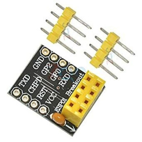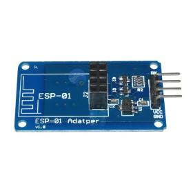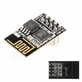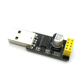


Product images are for informational purposes only and may vary slightly depending on the batch and supplier. Product specifications and prices may be subject to change without notice. We do our best to provide accurate and complete product specifications, but they may not be completely accurate. If you encounter any such situation, please let us know.
The product is intended for specialists and requires qualified and authorized personnel. The product does not include assembly/use instructions . Putting the product into operation by unqualified persons leads to the loss of the warranty according to the Terms and Conditions on the site.
The specified technical parameters (current, power, etc.) represent maximum allowable values under ideal operating conditions. For safe use and optimal lifespan, it is recommended to operate the product continuously at no more than 50% of the specified maximum values.
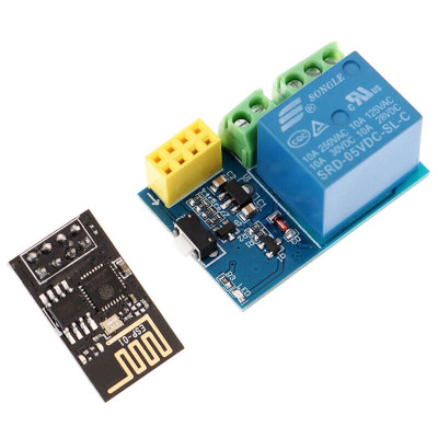
Relay kit with ESP8266, ESP-01
Compact solution for WiFi automation and remote control of consumers, combines a 5V relay with the ESP8266 ESP-01 module mounted directly in the socket. Includes 5V-3.3V step-down for powering the ESP, relay controlled from GPIO0 with LOW activation, support for Station and Access Point modes and UART communication for configuration and programming.
Shipping by Thursday 22 October
Buying this product earns you 0.23 € in loyalty points.

International fast shipping within EU. Free Shipping for orders above 100 EUR in most EU countries.

We ship from our stock within 24H

You earn points with every order, worth 5%.
This set combines a 5V powered relay module with an ESP8266 WiFi module of the ESP-01 type, for quick network automations. The relay module powers the ESP-01 board directly, which is inserted into the dedicated pins, and the ESP8266 can control the relay without other intermediary modules. It is a compact solution for remote control of various loads, ideal for smart home projects, simple automations, and IoT prototypes.
The relay module powers the esp01 board which is inserted directly onto the dedicated pins.
Allows automations via WiFi as the ESP module can directly control the relay.
Programming the ESP01 board requires a compatible programmer.
Specifications:
Supply voltage: 5V
ESP-01S supply voltage: 3.3V
Voltage conversion: integrated step-down from 5V to 3.3V for powering the ESP
Relay control pin: GPIO0
Active LOW: LOW = ON, HIGH = OFF
ESP8266 ESP-01 / ESP-01S Specifications:
Chip: ESP8266
WiFi standard: 2.4 GHz 802.11 b/g/n
WiFi modes: Station, Access Point, Station + Access Point
Logic voltage: 3.3V
Power supply: 3.3V
Communication interface: UART serial TTL
Antenna: PCB integrated on module
Onboard LED: present
Usage:
Power the module at 5V according to the markings on the board.
Mount the ESP-01 on the dedicated connector, with correct orientation.
Configure and program the ESP8266 through UART at 3.3V, do not use 5V on the pins. A programmer is required.
Connect the module to the WiFi network and set the control method, for example HTTP, MQTT, or integration with an automation platform.
Control the relay from the local network or remotely, depending on the configuration.
Work carefully when connecting loads, and for 230V voltages use insulation, enclosure, and appropriate protection measures.
Programming ESP-01 with FTDI:
Important: use FTDI set to 3.3V, not 5V.
ESP01 to Programmer Connection Table:
| ESP8266 ESP-01 / ESP-01S Pin | FTDI Converter Pin | Notes |
|---|---|---|
| RX | TX | Cross connection. |
| TX | RX | Cross connection. |
| VCC | VCC 3.3V | Power supply 3.3V. |
| CH_EN / EN | VCC 3.3V | Chip enable, keep it at 3.3V. |
| GPIO0 | GND | Connect to GND only for programming mode. |
| GND | GND | Common ground. |
Entering upload mode:
Connect all wires according to the table.
Make sure GPIO0 is connected to GND.
Power the board from the FTDI.
Press RESET if your module has a button, otherwise unplug and plug in the power again.
Upload code:
In Arduino IDE, select the board Generic ESP8266 Module.
Select the correct serial port.
In the code, replace SSID and PASSWORD with your WiFi network.
Click Upload.
After uploading, disconnect GPIO0 from GND, then restart the module.
Serial Monitor and verification:
Open Serial Monitor.
Set the baud rate to 115200.
Check messages about WiFi connection and the used address.
Mounting on the relay module:
Turn off the power.
Insert ESP-01 / ESP-01S into the relay module socket, with the correct orientation.
Power the relay module at 5V.
Access the URL set in the code, for example https://192.168.0.178/
Code:
See the Test section.
Produs destinat utilizarii in proiecte electronice, automatizari, prototipare, educatie si cercetare.
Produsul trebuie utilizat numai conform specificatiilor tehnice mentionate in descriere si/sau in documentatia produsului.
Avertismente generale de siguranta:
Nu utilizati produsul la tensiuni, curenti sau temperaturi peste valorile specificate.
Montajul si conectarea trebuie realizate de persoane cu cunostinte tehnice minime in domeniul electric/electronic.
Evitati scurtcircuitele, inversarea polaritatii si conectarea gresita a alimentarii.
Nu lasati produsul alimentat nesupravegheat in timpul testelor.
Produsul nu este jucarie si nu este destinat copiilor.
Pentru modulele electronice, se recomanda utilizarea in carcase, panouri sau montaje protejate, dupa caz.
Identificare produs:
Denumirea produsului, codul/SKU-ul si caracteristicile tehnice sunt mentionate in pagina produsului si/sau pe eticheta ambalajului.
Producator / Importator / Distribuitor:
Sigmanortec S.R.L.
Calea Bucuresti nr. 9, Targu Jiu, Gorj, Romania
E-mail: [email protected]
Website: www.sigmanortec.ro
Persoana responsabila in UE:
Sigmanortec S.R.L.
Calea Bucuresti nr. 9, Targu Jiu, Gorj, Romania
E-mail: [email protected]
Documentatie si siguranta:
Pentru informatii suplimentare, fise tehnice, declaratii de conformitate sau instructiuni, ne puteti contacta la [email protected].
Reviews (5) - Review moderation

Cu esp-ul nu am avut nicio problema, dar releul ramane rar blocat si trebuie manual ciocanit sa se dezlipeasca contactele, am observat ca mentinerea releului intr-o parte parca mai rareste lipirea contactelor.
Salutare am luat si eu un modul si nu ma descurc sa il foolosesc rog ajutor
Placuta ESP8266 nu are inscriptionate denumirile pinilor. In rest, super bun kitul, calitate/pret f bun.
Recomand
am comandat diverse kituri si am fost foarte multumit .
#include <ESP8266WiFi.h>


const char* ssid = "YOUR SSID";        // fill in your WiFi SSID
const char* password = "YOUR PASSWORD"; // fill in your WiFi password

#define RELAY 0 // relay connected to GPIO0 on ESP-01/ESP-01S

WiFiServer server(80);

static void sendPage(WiFiClient& client, bool relayIsOn)
{
  client.println("HTTP/1.1 200 OK");
  client.println("Content-Type: text/html; charset=utf-8");
  client.println("Connection: close");
  client.println();
  client.println("<!DOCTYPE HTML>");
  client.println("<html>");
  client.println("<head><meta name=\"viewport\" content=\"width=device-width, initial-scale=1\">");
  client.println("<title>ESP8266 RELAY Control</title></head>");
  client.println("<body style=\"font-family:Arial;\">");
  client.println("<h2>ESP8266 Relay Control</h2>");
  client.print("<p>Status: <b>");
  client.print(relayIsOn ? "ON" : "OFF");
  client.println("</b></p>");
  client.println("<p><a href=\"/RELAY=ON\">Turn ON</a></p>");
  client.println("<p><a href=\"/RELAY=OFF\">Turn OFF</a></p>");
  client.println("</body></html>");
}


void setup()
{
  Serial.begin(115200);

  pinMode(RELAY, OUTPUT);

  // Most ESP-01 relay boards are active LOW:
  // LOW  -> relay ON
  // HIGH -> relay OFF

  digitalWrite(RELAY, HIGH); // start with relay OFF

  Serial.println();
  Serial.print("Connecting to ");
  Serial.println(ssid);

  WiFi.mode(WIFI_STA);
  WiFi.begin(ssid, password);

  while (WiFi.status() != WL_CONNECTED)
  {
    delay(500);
    Serial.print(".");
  }


  Serial.println();
  Serial.println("WiFi connected.");
  Serial.print("IP address: ");
  Serial.println(WiFi.localIP());

  server.begin();
  Serial.println("Server started.");
  Serial.print("Open: http://");
  Serial.print(WiFi.localIP());
  Serial.println("/");
}

void loop()
{
  WiFiClient client = server.available();
  if (!client) return;

  Serial.println("New client.");

  while (!client.available())
  {

    delay(1);
    if (!client.connected()) return;
  }

  String request = client.readStringUntil('\r');
  client.flush();
  Serial.println(request);

  // Default state readback based on last write (simple approach)
  // If you need true state tracking, store it in a variable.

  static bool relayIsOn = false;

  if (request.indexOf("GET /RELAY=ON") != -1)
  {
    Serial.println("RELAY=ON");
    digitalWrite(RELAY, LOW);
    relayIsOn = true;
  }

  else if (request.indexOf("GET /RELAY=OFF") != -1)
  {
    Serial.println("RELAY=OFF");
    digitalWrite(RELAY, HIGH);
    relayIsOn = false;
  }


  sendPage(client, relayIsOn);


  delay(1);
  client.stop();
  Serial.println("Client disconnected.");
  Serial.println();
}