Product images are for informational purposes only and may vary slightly depending on the batch and supplier. Product specifications and prices may be subject to change without notice. We do our best to provide accurate and complete product specifications, but they may not be completely accurate. If you encounter any such situation, please let us know.
The product is intended for specialists and requires qualified and authorized personnel. The product does not include assembly/use instructions . Putting the product into operation by unqualified persons leads to the loss of the warranty according to the Terms and Conditions on the site.
The specified technical parameters (current, power, etc.) represent maximum allowable values under ideal operating conditions. For safe use and optimal lifespan, it is recommended to operate the product continuously at no more than 50% of the specified maximum values.
Acoustic control switch kit, clap switch, 5V, ICSK050A
Acoustic control module for simple automation, switches the output with each clap, generates a 5V signal upon detection and returns to LOW upon the second detection, 5VDC power supply, high sensitivity in the 3kHz range for fast response, ideal for use with a 5V relay to control lights or other consumers.
Shipping by Thursday 22 October
Buying this product earns you 0.91 RON in loyalty points.

International fast shipping within EU. Free Shipping for orders above 100 EUR in most EU countries.

We ship from our stock within 24H

You earn points with every order, worth 5%.
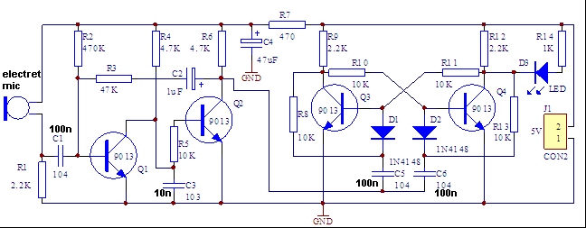
The acoustic clap switch module is a compact circuit that turns a hand clap into an electrical command, functioning as a bistable switch: on the first sound detection, the output goes HIGH and provides a 5V signal, and on the next detection it returns to LOW. The board integrates an electret microphone, a two-stage audio amplifier built with transistors Q1 and Q2, a bistable flip-flop circuit constructed with Q3 and Q4, as well as an indicator LED that visually signals the current output state. The R1 and C1 network limits the circuit’s frequency response, providing maximum sensitivity around 3kHz, exactly the range of the sharp sound produced by a clap, which reduces false triggering caused by background noise or speech. This filtering explains the module’s prompt and consistent response to clapping.
Power is supplied at 5VDC, and the low consumption allows operation from a stabilized mains supply, from a USB port, or directly from the 5V pin of a development board. The output available on connector J2 can drive a 5V relay module, which in turn can practically control any type of load: lighting fixtures, fans, pumps, solenoid valves, or other independent circuits. The same output can be read as a digital input by an Arduino Uno, Nano, Mega, or Pro Mini board, allowing the implementation of more complex automation, with delays, activation counting, or additional conditions. For boards that operate at 3.3V, such as ESP32, ESP8266, STM32, or Raspberry Pi Pico, the 5V signal must be adapted using a resistor divider or a logic level converter, otherwise there is a risk of damaging the input pin.
The module is suitable for touchless lighting control, for activating devices in workshops or in spaces where hands are occupied, for home automation projects, for models and demonstration stands, as well as for educational applications in which audio amplification and bistable flip-flop circuits are studied.
Specifications:
Supply voltage: 5VDC
Output type: bistable, toggles on each detection
Output logic level: 5V in active state, LOW in inactive state
Sensor: integrated electret microphone
Maximum sensitivity frequency: approximately 3kHz
Amplification: two stages with transistors (Q1, Q2)
Memory element: bistable flip-flop circuit (Q3, Q4)
Indicator: onboard LED for output state
Output connector: J2
Recommended load: 5V relay module or microcontroller digital input
Electronic schematic:
Pinout:
| Connector | Pin | Signal | Description |
|---|---|---|---|
| J1 | + | VCC | 5 VDC supply |
| J1 | - | GND | Ground |
| J2 | OUT | OUTPUT | 5 V signal in active state, LOW in inactive state |
| J2 | GND | GND | Common ground with the controlled circuit |
Instructions:
Connect the 5VDC supply to connector J1, observing the polarity marked on the board.
Check the initial state after power-up; the indicator LED should be off and the output should be LOW.
Clap once at a distance of 1 to 3 meters from the microphone and observe the LED turning on, at which point the output switches to 5V.
Clap again to return the output to LOW and turn off the LED.
To control a load, connect the OUT pin on J2 to the IN input of a 5V relay module and connect the grounds of the two modules together.
To integrate with a microcontroller, connect OUT to a digital input pin and GND to the board ground, using level shifting to 3.3V where applicable.
Place the module away from постоянные noise sources such as fans or speakers to avoid unwanted switching.
Test the response under real installation conditions before final mounting, because room acoustics affect the detection distance.
Warning: the module is powered at 5VDC and must never be connected directly to mains voltage. If the output controls a relay that switches 220VAC loads, the entire power side must be implemented by a qualified person, with proper isolation between the control side and the mains side, and work must be performed exclusively with the power disconnected from the distribution panel. Contact with mains voltage can cause electric shock or fire.
- Input Voltage
- 5VDC
- Input Voltage Type
- “DC” in Romanian can mean **“de ce”**, which translates to **“why”** in English.
Produs destinat utilizarii in proiecte electronice, automatizari, prototipare, educatie si cercetare.
Produsul trebuie utilizat numai conform specificatiilor tehnice mentionate in descriere si/sau in documentatia produsului.
Avertismente generale de siguranta:
Nu utilizati produsul la tensiuni, curenti sau temperaturi peste valorile specificate.
Montajul si conectarea trebuie realizate de persoane cu cunostinte tehnice minime in domeniul electric/electronic.
Evitati scurtcircuitele, inversarea polaritatii si conectarea gresita a alimentarii.
Nu lasati produsul alimentat nesupravegheat in timpul testelor.
Produsul nu este jucarie si nu este destinat copiilor.
Pentru modulele electronice, se recomanda utilizarea in carcase, panouri sau montaje protejate, dupa caz.
Identificare produs:
Denumirea produsului, codul/SKU-ul si caracteristicile tehnice sunt mentionate in pagina produsului si/sau pe eticheta ambalajului.
Producator / Importator / Distribuitor:
Sigmanortec S.R.L.
Calea Bucuresti nr. 9, Targu Jiu, Gorj, Romania
E-mail: [email protected]
Website: www.sigmanortec.ro
Persoana responsabila in UE:
Sigmanortec S.R.L.
Calea Bucuresti nr. 9, Targu Jiu, Gorj, Romania
E-mail: [email protected]
Documentatie si siguranta:
Pentru informatii suplimentare, fise tehnice, declaratii de conformitate sau instructiuni, ne puteti contacta la [email protected].
Reviews (4) - Review moderation

Jucarie faina. Usor de asamblat, functioneaza bine. desi e cam sensibil...
Super bun.
Practic
super