
Product images are for informational purposes only and may vary slightly depending on the batch and supplier. Product specifications and prices may be subject to change without notice. We do our best to provide accurate and complete product specifications, but they may not be completely accurate. If you encounter any such situation, please let us know.
The product is intended for specialists and requires qualified and authorized personnel. The product does not include assembly/use instructions . Putting the product into operation by unqualified persons leads to the loss of the warranty according to the Terms and Conditions on the site.
The specified technical parameters (current, power, etc.) represent maximum allowable values under ideal operating conditions. For safe use and optimal lifespan, it is recommended to operate the product continuously at no more than 50% of the specified maximum values.
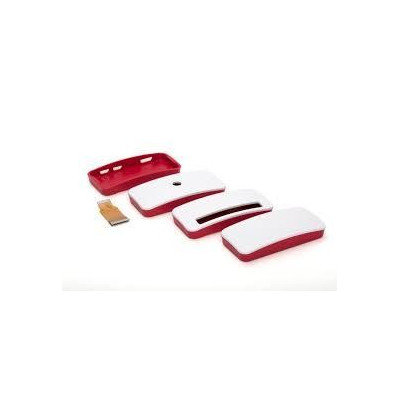
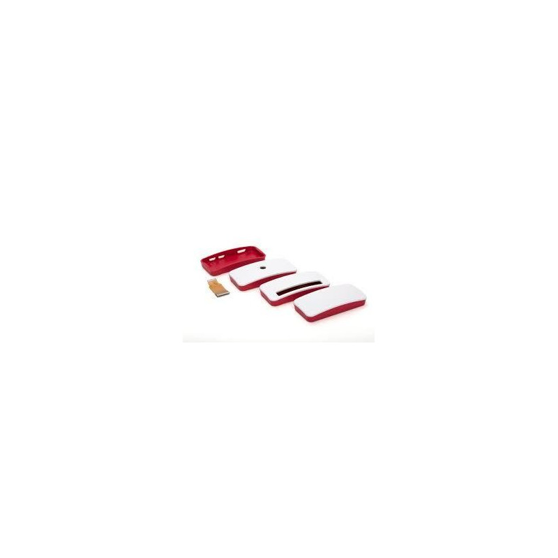
Raspberry Pi Zero Case, Red and White ABS, 3 Interchangeable Covers, Short Camera Cable, 79 x 38 x 15 mm
Protects and organizes the Raspberry Pi Zero in compact projects, offering interchangeable top covers for quick access to connectors and ventilation, includes an adapter for mounting the camera, ensures stable fixing of the board and cables, lightweight and durable construction for daily use in technical and hobby applications.
Shipping by Wednesday 11 November
Buying this product earns you 0.75 RON in loyalty points.

International fast shipping within EU. Free Shipping for orders above 100 EUR in most EU countries.

We ship from our stock within 24H

You earn points with every order, worth 5%.
ABS plastic case for the Raspberry Pi Zero, Raspberry Pi Zero W and Raspberry Pi Zero 2 W boards protects the board and leaves exposed only what the project needs. The set includes a red base and three interchangeable white covers (flat, GPIO and camera), plus a short camera cable, which allows you to change the case configuration without replacing it. It is suitable for small servers, automation, projects with sensors connected to the GPIO pins and miniature surveillance cameras.
The base has cutouts for the board's side connectors and for the microSD card. The flat cover closes the case completely, the GPIO cover has a slot through which the top GPIO pins remain accessible, and the camera cover has a hole for the lens. The camera cover is made for the Raspberry Pi Camera Module 1 and 2, in standard and NoIR versions. The Camera Module 3 does not fit mechanically with this cover. The short cable is 38 mm long and replaces the standard long cable in the limited space inside the case.
The main features include the red base with three interchangeable white covers, the short camera cable, the 4 rubber feet for stability on the work surface and the compact dimensions of 79 x 38 x 15 mm. The case is a passive accessory, with no power supply of its own, and the board and camera are not included.
The case is made for the Raspberry Pi Zero, Raspberry Pi Zero W and Raspberry Pi Zero 2 W boards. The camera connector is present on the Raspberry Pi Zero v1.3, the Zero W and the Zero 2 W, so mounting the camera in the case is possible only on these boards. A board with soldered pins (such as the Zero WH) fits only with the GPIO cover.
Specifications:
Product type: Case for Raspberry Pi Zero boards
Compatible boards: Raspberry Pi Zero, Zero W, Zero 2 W
Material: ABS
Color: Red base, white covers
Included covers: 3 (flat, GPIO, camera)
Cameras compatible with the camera cover: Raspberry Pi Camera Module 1 and 2, standard and NoIR
Camera cable: Short, 38 mm
Rubber feet: 4
Dimensions: 79 x 38 x 15 mm
Layout:
| Element | Function |
|---|---|
| Red base | Holds the Raspberry Pi Zero board and has cutouts for the side connectors (mini HDMI, micro USB, microSD card). |
| Flat cover | Closes the case completely and protects the board when accessories are not needed. |
| GPIO cover | Has a slot through which the GPIO pins remain accessible, for wires, HATs or boards with soldered pins. |
| Camera cover | Has a hole for the lens of the Raspberry Pi Camera Module 1 or 2. |
| Short camera cable | Connects the camera connector of the board to the camera board in the small space inside the case. |
| Rubber feet | Are applied to the bottom of the base and prevent the case from sliding. |
Usage:
Shut down the Raspberry Pi Zero board, disconnect the power supply and remove the microSD card if it is inserted.
Work with dry hands and avoid touching the components on the board, to prevent exposing it to electrostatic discharge.
Choose the cover according to the project. Use the flat cover for an assembly without accessories, the GPIO cover for wires, pins or HATs, and the camera cover when mounting a Module 1 or 2 camera.
If the board has soldered pins, use only the GPIO cover, because the tall pins do not fit under the other covers.
To mount the camera, open the latch of the board's camera connector, insert the short cable straight and with the contacts aligned, then close the latch. Connect the other end to the camera board in the same way.
Place the board in the base, with the connectors aligned with the side cutouts. The board must sit flat, without forcing.
Place the chosen cover over the base and press gently until it seats evenly. With the camera cover, check that the lens is aligned with the hole before pressing.
Do not force the cover if it does not fit. Check that the camera cable or a connector is not pinched.
Apply the 4 rubber feet to the bottom of the base, then insert the microSD card, connect the power supply through the side cutouts and switch on the board.
For high loads over long periods, especially with the flat cover, keep in mind that it restricts air circulation, and place the case in a well-ventilated location.
- Dimensions
- 79 x 38 x 15 mm
- Material
- ABS
- Type
- Case for Raspberry Pi Zero boards
- Colour
- Red base, white covers
- Cable length
- 38 mm
- Compatibility
- Raspberry Pi Zero, Zero W, Zero 2 W
Produs destinat utilizarii in proiecte electronice, automatizari, prototipare, educatie si cercetare.
Produsul trebuie utilizat numai conform specificatiilor tehnice mentionate in descriere si/sau in documentatia produsului.
Avertismente generale de siguranta:
Nu utilizati produsul la tensiuni, curenti sau temperaturi peste valorile specificate.
Montajul si conectarea trebuie realizate de persoane cu cunostinte tehnice minime in domeniul electric/electronic.
Evitati scurtcircuitele, inversarea polaritatii si conectarea gresita a alimentarii.
Nu lasati produsul alimentat nesupravegheat in timpul testelor.
Produsul nu este jucarie si nu este destinat copiilor.
Pentru modulele electronice, se recomanda utilizarea in carcase, panouri sau montaje protejate, dupa caz.
Identificare produs:
Denumirea produsului, codul/SKU-ul si caracteristicile tehnice sunt mentionate in pagina produsului si/sau pe eticheta ambalajului.
Producator / Importator / Distribuitor:
Sigmanortec S.R.L.
Calea Bucuresti nr. 9, Targu Jiu, Gorj, Romania
E-mail: [email protected]
Website: www.sigmanortec.ro
Persoana responsabila in UE:
Sigmanortec S.R.L.
Calea Bucuresti nr. 9, Targu Jiu, Gorj, Romania
E-mail: [email protected]
Documentatie si siguranta:
Pentru informatii suplimentare, fise tehnice, declaratii de conformitate sau instructiuni, ne puteti contacta la [email protected].
Reviews (1) - Review moderation

The Raspberry Pi Zero case is a red and white plastic case for Raspberry Pi Zero, Raspberry Pi Zero W and Raspberry Pi Zero 2 W boards. It consists of a base and three interchangeable covers (flat, GPIO and camera), and the set also includes a short camera cable. Choose the cover according to your project: closed for protection, with a slot for access to the GPIO pins, or with a hole for the camera.
This tutorial uses a Raspberry Pi Zero board that you mount in the case. The product is a mechanical accessory, so it does not need a program and has no power supply of its own. You will learn how to choose the right cover, how to mount the board and, if you want, the camera, and what the limits of the case are.
How it works:
The case has two parts. The base has the cutouts for the board connectors, and one of the three covers is placed on top. The cover determines what remains accessible after assembly, so you can change the configuration at any time without modifying the base.
The flat cover fully encloses the board and is suitable when the Raspberry Pi Zero runs a program without accessories, for example a server or a small automation device. The GPIO cover has a slot through which the top GPIO pins remain accessible, so it is used when you connect wires, a HAT or a board with soldered pin headers. The camera cover has a hole for the lens and, together with the short cable from the set, allows the camera to be mounted inside the case.
The short camera cable, 38 mm long, replaces the standard long cable. One end connects to the camera connector of the Raspberry Pi Zero board, and the other end to the camera board. The camera connector is present on the Raspberry Pi Zero v1.3, the Zero W and the Zero 2 W. The camera cover is made for the Raspberry Pi Camera Module 1 and 2, standard and NoIR. The Camera Module 3 and the HQ Camera do not fit mechanically with it.
The dimensions of the assembled case are approximately 79 x 38 x 15 mm.
Connection:
No wires are connected to this product and it has no power supply of its own. The table shows which part is placed on which element and what it is used for. Before assembly, disconnect the power from the Raspberry Pi Zero board and remove the microSD card if it is inserted.
| Product part | Connects to | Role |
|---|---|---|
| Base | Raspberry Pi Zero, Zero W or Zero 2 W board | Supports the board and leaves the side connectors free (mini HDMI, micro USB, microSD card) |
| Flat cover | Base | Closes the case completely |
| GPIO cover | Base | Leaves access to the GPIO pins through the top slot |
| Camera cover | Base | Has a hole for the camera lens |
| Short camera cable | Camera connector of the board and the camera board | Connects the camera to the board in the small space inside the case |
| Rubber feet | Bottom of the base | Prevent the case from sliding |
Assembly:
Turn off and disconnect the Raspberry Pi Zero board from the power supply. Work with dry hands and avoid touching the components on the board, to avoid exposing it to electrostatic discharge.
Choose the cover according to the use. For a project without accessories, take the flat cover. For wires, pins or a HAT, take the GPIO cover. For the camera, take the cover with the hole.
If you use the GPIO cover, check whether the board has soldered pin headers. A board with soldered pin headers, such as the Zero WH, fits only with the GPIO cover, because the tall pins do not fit under the other covers.
If you mount the camera, open the latch of the camera connector on the board, insert the short cable with the contacts aligned with those of the connector and close the latch. Then connect the other end to the camera board in the same way. The cable must enter straight and without forcing.
Place the board in the base, with the connectors aligned with the side cutouts. The board must sit flat, without being forced.
Put the chosen cover over the base and press gently until it seats evenly. For the camera cover, check that the lens is in line with the hole before pressing. Do not force the cover if it does not go in. Instead, check that a cable or a connector is not caught.
Apply the rubber feet to the bottom of the base, then connect the power supply and the microSD card through the side cutouts and power on the board.
Usage example:
A simple example is a miniature surveillance camera with the Raspberry Pi Zero W. Mount a Zero W board and a Raspberry Pi Camera Module 2 in the case, using the short cable from the set and the camera cover. The lens must be visible through the hole in the cover.
Insert the microSD card with the installed system, connect the power through the micro USB port and power on the board. After startup, check from the system that the board sees the camera and take a test photo. If the image appears, the assembly is correct.
For another project, for example a sensor connected to the GPIO pins, change the cover to the GPIO one. Turn off the board, remove the camera cover, disconnect the camera cable if it is no longer needed and put on the cover with the slot, through which you route the wires to the sensor.
Common problems:
The cover does not seat completely. Usually the board does not sit flat in the base, a connector is not aligned with the cutout or the camera cable is crushed. Remove the cover, reseat the board and the cable and try again without force.
The board with soldered pin headers does not fit under the cover. The flat cover and the camera cover have no space for tall pins. Use the GPIO cover or leave the board without soldered pin headers.
The camera is not detected. The usual causes are the cable inserted in reverse or not fully inserted, the latch not closed or an incompatible camera. Turn off the board, reconnect the cable at both ends and check that you are using a Module 1 or 2 camera. The Raspberry Pi Zero v1.2 board has no camera connector.
The Camera Module 3 or the HQ Camera does not fit with the cover. The camera cover is made for Modules 1 and 2. For the other cameras, use the flat or GPIO cover and mount the camera outside the case.
The board heats up more inside the closed case. The flat cover limits air circulation. For heavy, long-duration workloads, especially on the Zero 2 W, consider the GPIO cover or additional cooling outside the case.
Limitations and tips:
The case does not include the Raspberry Pi Zero board or the camera. It is a passive accessory, with no power supply of its own, no fan and no heatsink.
The camera cover accepts only the Module 1 and 2 cameras, standard or NoIR. The short cable is 38 mm, so the camera must sit close to the board, inside the cover.
The covers are easy to change, so you can use the flat cover for the final assembly and the GPIO cover while you test a project with wires or a HAT.