

Product images are for informational purposes only and may vary slightly depending on the batch and supplier. Product specifications and prices may be subject to change without notice. We do our best to provide accurate and complete product specifications, but they may not be completely accurate. If you encounter any such situation, please let us know.
The product is intended for specialists and requires qualified and authorized personnel. The product does not include assembly/use instructions . Putting the product into operation by unqualified persons leads to the loss of the warranty according to the Terms and Conditions on the site.
The specified technical parameters (current, power, etc.) represent maximum allowable values under ideal operating conditions. For safe use and optimal lifespan, it is recommended to operate the product continuously at no more than 50% of the specified maximum values.
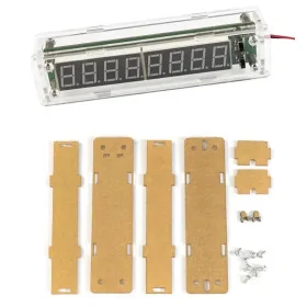
Crystal frequency tester kit for PIC16F628A, 1Hz–50MHz, 5-digit display, 5–9V DC
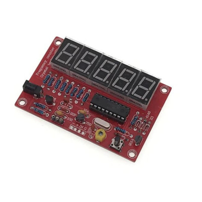
DIY tester for quick crystal frequency check, useful in troubleshooting and electronic projects. Measures crystals between 1Hz and 50MHz, operates at 5-9VDC, has auto shut-off after 15 seconds of no variation to save power, includes compact 80x53mm PCB and requires assembly.
Buying this product earns you 2.23 RON in loyalty points.

International fast shipping within EU. Free Shipping for orders above 100 EUR in most EU countries.

We ship from our stock within 24H

You earn points with every order, worth 5%.
The DIY crystal tester and frequency meter kit measures the frequency of quartz crystals between 1 Hz and 50 MHz and displays the value directly on a 5-digit display. The crystal to be tested is inserted into the socket on the board, and the frequency appears on the display. The kit is suitable for checking recovered crystals or crystals with erased markings, for troubleshooting, for laboratory use, and for educational projects. The board also has an IN input for an external signal, with a maximum level of 5 V.
Frequency counting is performed by the PIC16F628A microcontroller, which uses a 20 MHz crystal with an adjustable capacitor as its time base. The S9014 and S9018 transistors amplify the signal before counting. The kit has automatic shutoff. If the frequency does not vary consistently for 15 seconds, the display turns off to reduce power consumption.
Among the main features are the five 7-segment displays, the 3-pin socket for the crystal under test, the power and input pads marked -, + and IN, the 5 V 7550A-1 regulator, the tactile button, the adjustable capacitor next to the 20 MHz crystal, and four mounting holes. Power is supplied at 5 - 9 VDC through the DC jack with center positive or through the + and - pads.
The kit operates independently, without a development board and without programming. Assembly by soldering is required, and all components are through-hole.
Specifications:
Supply voltage: 5 - 9 VDC
Microcontroller: PIC16F628A
Measured frequency range: 1 Hz - 50 MHz
Display: 5-digit 7-segment
Time base: 20 MHz crystal with adjustable capacitor
Automatic shutoff: After 15 seconds without consistent frequency variation
Power connector: DC jack with center positive or + and - pads
Product type: Assembly kit
Dimensions: 80 x 53 mm
Layout:
| Element | Function |
|---|---|
| DC jack | Power input at 5 - 9 VDC, center positive. |
| -, + and IN pads | The - and + pads are connected to power, and IN is the input for an external signal, with a maximum level of 5 V. |
| 3-pin socket | The socket into which the crystal under test is inserted. |
| 7-segment displays | Five digits (D1 - D5) on which the measured frequency is shown. After automatic shutoff, the display remains off until power is turned on again. |
| PIC16F628A microcontroller | Counts pulses, drives the display, and manages automatic shutoff. |
| 20 MHz crystal | The time base of the frequency meter. |
| Adjustable capacitor | Fine adjustment of the 20 MHz time-base oscillator frequency, which affects the accuracy of the displayed value. |
| S9014 and S9018 transistors | Amplify the input signal and the signal from the crystal under test. |
| 7550A-1 regulator | Stabilizes the 5 V supply for the circuit. |
| Tactile button | Control button for the kit, mounted next to the adjustable capacitor. |
| Mounting holes | Four holes for securing the board. |
Pinout:
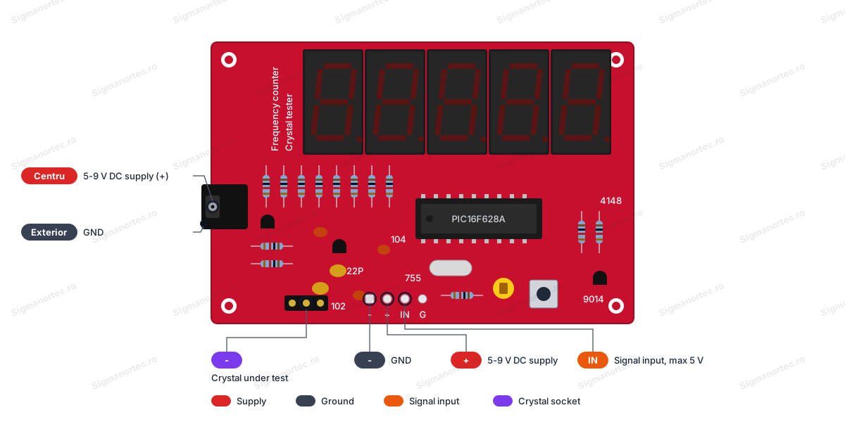
| Connector | Pin | Function |
|---|---|---|
| DC jack | Center | 5 - 9 VDC power supply (positive) |
| DC jack | Outer | GND |
| Power pads | + | 5 - 9 VDC power supply |
| Power pads | - | GND |
| Input pad | IN | External signal input, maximum 5 V |
| 3-pin socket | - | Crystal under test |
Usage:
Assemble the kit by soldering the components in the marked locations on the board, respecting the orientation of the transistors, diodes, regulator, and integrated circuit.
Solder the 3-pin socket into the unmarked holes next to the -, + and IN pads, not into the marked pads.
Power the kit with 5 - 9 VDC, either through the DC jack with center positive or through the + and - pads, observing polarity.
Do not exceed 9 VDC on the supply, and do not apply signals above 5 V to the IN input.
Insert the crystal to be tested into the 3-pin socket and read the frequency on the display.
If the display turns off after 15 seconds without consistent frequency variation, restart the power supply and repeat the measurement.
To measure an external signal, connect the signal to the IN pad, with ground shared with the kit’s supply.
Leave the adjustable capacitor next to the 20 MHz crystal in the installed position and do not turn it unless the displayed value for a known frequency differs from the expected one, and after each small adjustment repeat the measurement to see the effect of the setting.
Use the tactile button as the kit’s control button after assembly is complete and the unit is powered.
The kit has been tested only for crystal measurement.
For stable results, use a clean power supply and crystals with clean terminals, fully inserted into the socket.
- Supply voltage
- 5-9 V DC
- Dimensions
- 80 x 53 mm
- Type
- Kit requiring assembly
- Connector type
- DC jack
- Display
- 5 digits, 7-segment
- Microcontroller
- PIC16F628A
Produs destinat utilizarii in proiecte electronice, automatizari, prototipare, educatie si cercetare.
Produsul trebuie utilizat numai conform specificatiilor tehnice mentionate in descriere si/sau in documentatia produsului.
Avertismente generale de siguranta:
Nu utilizati produsul la tensiuni, curenti sau temperaturi peste valorile specificate.
Montajul si conectarea trebuie realizate de persoane cu cunostinte tehnice minime in domeniul electric/electronic.
Evitati scurtcircuitele, inversarea polaritatii si conectarea gresita a alimentarii.
Nu lasati produsul alimentat nesupravegheat in timpul testelor.
Produsul nu este jucarie si nu este destinat copiilor.
Pentru modulele electronice, se recomanda utilizarea in carcase, panouri sau montaje protejate, dupa caz.
Identificare produs:
Denumirea produsului, codul/SKU-ul si caracteristicile tehnice sunt mentionate in pagina produsului si/sau pe eticheta ambalajului.
Producator / Importator / Distribuitor:
Sigmanortec S.R.L.
Calea Bucuresti nr. 9, Targu Jiu, Gorj, Romania
E-mail: [email protected]
Website: www.sigmanortec.ro
Persoana responsabila in UE:
Sigmanortec S.R.L.
Calea Bucuresti nr. 9, Targu Jiu, Gorj, Romania
E-mail: [email protected]
Documentatie si siguranta:
Pentru informatii suplimentare, fise tehnice, declaratii de conformitate sau instructiuni, ne puteti contacta la [email protected].
Reviews (5) - Review moderation

Foarte util kit, recomand cu caldura
- Frecvenametrul funcsioneaza excelent, mult peste aateptari. Comparat cu un frecvenametru profesional (Rohde & Schwarz HM8123 Frequency Counter) are o abatere de sub 300 Hz an gama megahertzilor si o deriva de circa 2 ... 8 Hz an gama kilozertzilor, dupa o ora de funcsionare. an plus este rezilient. Noi al utilizam pentru masuratori nepretensioase antr-un laborator studenaesc (studii de licenaa), an care, an mod inevitabil, apar incidente de masurare, de alimentare si de conectare la sursele de semnal. A rezistat multor aagresiunia si neglijenae, chiar montat pe un panou adeschisa (neprotejat an mod special). Alimentarea o realizam din acumulator de 12 V, prin regulator liniar de tensiune (reglat pentru 6,3 V, doar putin peste limita inferioara de lucru a stabilizatorului HT7550 de pe placa, limita determinata anterior montarii). Determinarile de precizie si stabilitate an funcsionare mai sus mensionate au fost realizate an condisiile unei astfel de alimentari. - Oscilatorul Colpitts este modest si de aceea al utilizam cu precausie. Este analt dependent de valoarea tensiunii de alimentare si funcsioneaza instabil cu cristale de cuara ce au frecvenae de rezonanaa sub 4 MHz. Testarea s-a efectuat atat cu cistale arecentea, cat si cu unele de fabricatie sovietica, an montura din calit (destinate aplicatiilor de radiofrecvenaa). Acestea din urma oscileaza stabil pana la circa 1 MHz daca alimentarea montajului se realizeaza la 7,5 V. - Codul pentru microcontroller este disponibil an WEB si poate fi modificat. Este preferabil ca noua varianta *.hex sa fie ancarcata antr-un microcontroller nou.
Toate produsele pe care le-am primit de la dumneavoastra au fost foarte bune..Aaa este si acest kit..Toate au funcsionat perfect dupa montaj..
Funcsioneaza foarte bine aaa cum e in pachet. Dar recomand un update de firmware de aici: firmware change to improve resolution of a popular 1Hz-50MHz Digital LED DIY Kits Crystal Oscillator Frequency Counter Tester sold on Ebay and other sites https://github.com/TheHWcave/PIC-freq.counter-modification
L-am testat si indica bine pana pe la 2,5 MHz ,chiar si mai sus spre 4MHz daca semnalul este bun - pe toate formele de semnal. Pentru ce l-am luat eu e foarte bun - pentru gama audio 0-20000 Hz.Este cu autoscalare dar, daca nu ai alta aparatura de verificare te poti insela ca nu stii ce iti indica KHz , Mhz ...Are si un tester de cristale quartz al carui oscilator functioneaza corect in gama 5 - 26 MHz. Livrare rapida , comunicare buna ,seriozitate.
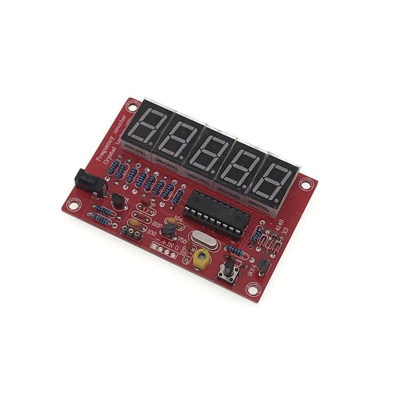
This tutorial shows how to start up and use the PIC16F628A crystal tester and frequency counter kit, 1 Hz - 50 MHz. The kit is a standalone instrument with its own microcontroller, so the tutorial does not use the development board and does not require any program. It is powered by a 9 V 6F22 battery or by a 5 - 9 VDC adapter.
In projects, the kit is useful for checking quartz crystals before assembly, for identifying those with a worn-off marking, and for troubleshooting oscillators. The frequency appears directly on the five 7-segment displays.
How it works:
A quartz crystal oscillates at its own natural frequency when it is placed in an oscillator circuit. In this kit, the S9014 and S9018 transistors amplify the oscillation signal, and the PIC16F628A microcontroller counts how many pulses appear within a known time interval, called the gate time.
The formula used is f = N / t, where f is the frequency, N is the number of pulses counted and t is the gate time. For example, if N = 270000 pulses are counted in t = 0.01 s, the frequency is 270000 / 0.01 = 27000000 Hz, that is 27 MHz. The kit changes the display range and the gate time automatically depending on the frequency, so you have nothing to select.
The measurement accuracy depends on the time base. This is a 20 MHz crystal, with a period of 1 / 20000000 = 50 ns, and an adjustable capacitor allows fine tuning of its frequency. If the displayed frequency does not vary consistently for 15 seconds, the display switches off to reduce consumption.
Connection:
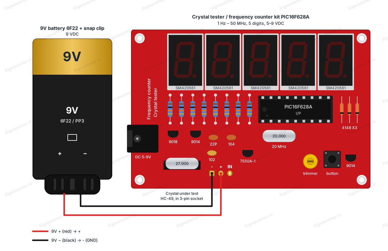
Power the kit at 5 - 9 VDC, either with a 9 V battery through the clip, or with an adapter through the DC jack with the centre pin positive. The battery clip is soldered to the + and - pads, with the red wire to + and the black wire to -. Do not exceed 9 V and respect the polarity. The circuit does not need a level converter or other external components, and the 7550A-1 regulator produces the 5 V voltage for the microcontroller. To measure a crystal, do not connect anything to IN. If you measure an external signal, its level at IN must be at most 5 V, not 5 - 9 V as for the power supply, and the signal ground is connected to the - pad.
| Product pin | Connects to | Role |
|---|---|---|
| + | 9V 6F22 battery positive (red wire) | Power supply 5 - 9 VDC |
| - | 9V 6F22 battery negative (black wire) | Ground (GND) |
| DC jack | Adapter with centre pin positive, 5 - 9 VDC | Alternative power supply, in place of the battery |
| 3-pin socket | HC-49 quartz crystal to be tested | The crystal whose frequency is measured |
| IN | Not connected for the crystal test. External signal of maximum 5 V when measuring a signal | Input for external signal |
Buttons, adjustments and indicators:
| Element | What it does | How to use it |
|---|---|---|
| 7-segment displays D1 - D5 | Show the measured frequency on five digits. | Read the value after inserting the crystal. After the automatic shutdown they stay off until the power is restarted. |
| Adjustable capacitor next to the 20 MHz crystal | Finely adjusts the frequency of the time base, on which the accuracy of the displayed value depends. | Leave it in the mounted position. Turn it slightly, with an insulated screwdriver, only if a known crystal shows an incorrect reading. |
| Touch button | Control button of the kit, mounted next to the adjustable capacitor. | Not needed for crystal testing. A long press, of about one second, opens the menu for programming the frequency offset, used with receivers and transceivers. |
The adjustable capacitor. Start from the position in which it was mounted. Insert a crystal whose frequency you know for certain, for example 20 MHz or 27 MHz, and read the value. If the value differs from the expected one, turn the capacitor very little with an insulated screwdriver, then repeat the measurement. The adjustment has worked when the displayed value matches that of the reference crystal. Make small turns and check after each one, because a large turn spoils the adjustment.
The touch button. You do not use it for checking crystals. If you press it long by mistake and the menu appears on the display, exit it without changing anything, then restart the power supply. The offset menu is only useful when the kit measures the frequency of a receiver's local oscillator, to which an intermediate frequency is added or from which it is subtracted.
Configuration:
The kit does not need configuration for crystal testing. After assembly, check that the 3-pin socket is soldered in the unmarked holes next to the -, + and IN pads, that the integrated circuit is well seated in the socket, and that there are no solder bridges between pins.
Connect the power supply with the correct polarity and insert a known crystal into the socket. The crystal can be a 20 MHz or a 27 MHz one, for example. Read the value on the display. With a 27 MHz crystal, the display shows 27.00, that is 27.00 MHz. If you have a safe reference frequency, adjust the adjustable capacitor slightly until the displayed value matches the reference.
| Operating mode | How to use it | Notes |
|---|---|---|
| Crystal tester | The crystal is inserted into the 3-pin socket | Range 1 Hz - 50 MHz, tested mode |
| Frequency counter | The signal is applied to the IN pad | Maximum 5 V at the input |
| Automatic shutdown | Activates by itself | The display turns off after 15 seconds without consistent variations |
Usage example:
You have a crystal salvaged from an old device, with a worn-off marking, and you want to find its frequency. Leave the adjustable capacitor in the mounted position, do not press the touch button and leave IN unconnected. Power the kit from a 9 V battery, with red to + and black to -.
Insert the crystal into the 3-pin socket, fully, with the terminals straight. The display shows the frequency, for example 27.00 for a 27 MHz crystal. Note the value and mark the crystal.
If you do not touch anything and the value does not change, the display switches off after 15 seconds. For the next crystal, restart the power supply, insert the new crystal and repeat the measurement.
Common problems:
The display does not light up at all. The usual cause is power supply with the wrong polarity or below 5 V, or a poor contact at the battery clip. Check the polarity, the voltage and the solder joints of the DC jack or of the pads.
The display switched off after a few seconds. This is the automatic shutdown, activated when the frequency does not vary consistently for 15 seconds. Restart the power supply to continue.
No value is read when you insert the crystal. The likely cause is the 3-pin socket soldered on the pads marked -, + and IN instead of the unmarked holes next to them, or a defective crystal. Check the position of the socket and try a crystal that you know works.
Some segments are missing or wrong digits appear. These are usually cold solder joints or bridges on the displays, on the resistors or on the integrated circuit. Redo the solder joints and check that the integrated circuit is fully inserted into the socket.
The value differs from the one marked on the crystal. First check a known crystal, for example one of 20 MHz or 27 MHz, then adjust the adjustable capacitor slightly. At the ends of the measuring range, for example with crystals of around 4 MHz or 48 MHz, the readings may be less reliable.
The value differs by a constant frequency amount from the crystal. A possible cause is an offset left programmed in the menu opened with the touch button. Enter the menu with a long press, choose the return of the offset to zero, then repeat the measurement.
Limitations and tips:
The declared range is 1 Hz - 50 MHz, and the display has only 5 digits, so the resolution is limited. The accuracy depends on the 20 MHz crystal and on the adjustment of the adjustable capacitor. The kit was tested only for measuring crystals, so for measuring external signals check the values against a source of known frequency.
Do not apply signals above 5 V to IN and do not power the kit above 9 V. It is not a calibrated laboratory instrument, but a quick tester for checking crystals.
For portable use you can use a 9 V battery or a 5 V source. After assembly you can mount the kit in an enclosure, using the four mounting holes, to protect the solder joints and the display.