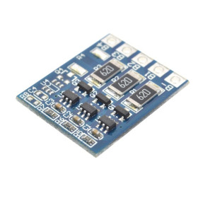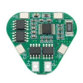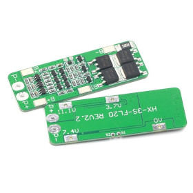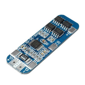

Product images are for informational purposes only and may vary slightly depending on the batch and supplier. Product specifications and prices may be subject to change without notice. We do our best to provide accurate and complete product specifications, but they may not be completely accurate. If you encounter any such situation, please let us know.
The product is intended for specialists and requires qualified and authorized personnel. The product does not include assembly/use instructions . Putting the product into operation by unqualified persons leads to the loss of the warranty according to the Terms and Conditions on the site.
The specified technical parameters (current, power, etc.) represent maximum allowable values under ideal operating conditions. For safe use and optimal lifespan, it is recommended to operate the product continuously at no more than 50% of the specified maximum values.
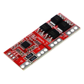
BMS 3S Module, 12.6V, 20A, for 18650 Cells
BMS board for 3S Li-ion packs, provides charge and discharge protection for 3 18650 cells, with a total voltage of 12.6V at full charge. Offers overcharge protection 4.25-4.35V and overdischarge protection 2.3-3.0V per cell, supports current up to 20A, has internal resistance below 150mAh and compact size 51 x 23 x 4 mm.
Buying this product earns you 0.50 RON in loyalty points.

International fast shipping within EU. Free Shipping for orders above 100 EUR in most EU countries.

We ship from our stock within 24H

You earn points with every order, worth 5%.
The BMS 3S module is a protection board for lithium-ion battery packs made of 3 cells connected in series, with a total voltage of 12.6 V at full charge. The board monitors the cell voltage during charging and discharging and interrupts the circuit when the safety limits are exceeded. It is suitable for battery packs built from 3 cells of type 18650, used in motor tools, drills, lamps and other applications powered at 12 V.
Overcharge protection acts per cell, at a value between 4.25 and 4.35 V, and overdischarge protection acts per cell, at a value between 2.3 and 3.0 V. The maximum operating current is 20 A, switched by four power MOSFET transistors mounted on the board.
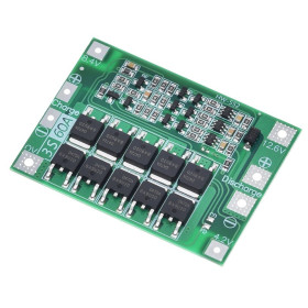
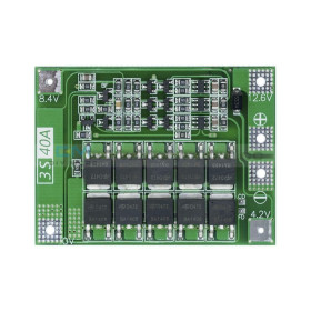
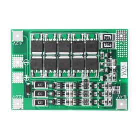
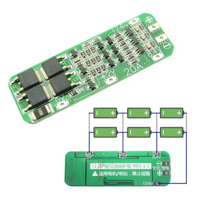
The main features include the four cell connection pads, marked 0V, 4.2V, 8.4V and 12.6V, two pads for charging and discharging, marked + and -, and the power MOSFET transistors. The board has no power supply of its own, it is powered directly by the battery pack to which it is connected.
Specifications:
Battery configuration: 3S (3 lithium-ion cells in series)
Charging voltage: 12.6 V
Maximum operating current: 20 A
Overcharge protection per cell: 4.25 - 4.35 V
Overdischarge protection per cell: 2.3 - 3.0 V
Recommended cells: 18650
Dimensions: 60 x 22 x 4 mm
Layout:

| Element | Function |
|---|---|
| Pad 0V | Connects to the negative terminal of the first cell in the pack. |
| Pad 4.2V | Connects to the point between the first and the second cell, for monitoring the voltage of the first cell. |
| Pad 8.4V | Connects to the point between the second and the third cell, for monitoring the voltage of the second cell. |
| Pad 12.6V | Connects to the positive terminal of the last cell, for monitoring the voltage of the third cell and of the pack. |
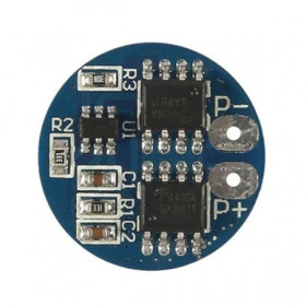
| Charge / discharge pads (+ and -) | Lead to the charger and to the load. The + and - terminals are marked on the board. |
| Power MOSFET transistors (4 pieces) | Switch the pack current and interrupt the circuit when one of the protections is activated. |
| SMD protection circuits and components | Measure the voltage of each cell and control the MOSFET transistors. |
The board has no buttons, potentiometers, jumpers, switches or LEDs, so it does not require any adjustment.
Pinout:
| Connector | Pin | Function |
|---|---|---|
| Battery pads | 0V | Negative of the first cell |
| Battery pads | 4.2V | Point between cell 1 and cell 2 |
| Battery pads | 8.4V | Point between cell 2 and cell 3 |
| Battery pads | 12.6V | Positive of the last cell |
| Charge / discharge pads | + | Positive output to the charger and the load |
| Charge / discharge pads | - | Negative output to the charger and the load |
Usage:
Verify that the battery pack consists of 3 lithium-ion cells connected in series and that each cell has a voltage within the working range of the board. If a cell is made of several cells connected in parallel, treat the parallel group as a single cell.
Connect the board pads to the pack in increasing order of voltage: 0V to the negative of the first cell, 4.2V to the point between cells 1 and 2, 8.4V to the point between cells 2 and 3, and 12.6V to the positive of the last cell.
Respect the polarity and do not swap the wires on the pads marked with voltage. A wrong connection can destroy the board and the batteries.
Connect the load and the charger to the charge and discharge pads, respecting the + and - markings.
Charge the pack only with a charger for 3 lithium-ion cells, with an output voltage of 12.6 V. Do not apply a higher charging voltage.
Do not exceed the maximum current of 20 A. If the cooling of the board is poor, use a lower current, because the MOSFET transistors heat up at high currents.
Avoid short-circuiting the output. The board is built with protection, but a repeated short circuit can damage it.
For stable results, solder the wires quickly and with a cross-section sufficient for the current used, and after soldering check the voltage of each cell with a multimeter before connecting the load.
If the protection interrupts the output, disconnect the load and check the cell voltage. To restart, charge the pack.
- Dimensions
- 51 x 23 x 4 mm
- Maximum current
- 20 A
- Charging voltage
- 12.6 V
- Configuration
- 3S
- Discharge protection voltage
- 2.3-3.0 V
- Overcharge protection voltage
- 4.25-4.35 V
Produs destinat utilizarii in proiecte electronice, automatizari, prototipare, educatie si cercetare.
Produsul trebuie utilizat numai conform specificatiilor tehnice mentionate in descriere si/sau in documentatia produsului.
Avertismente generale de siguranta:
Nu utilizati produsul la tensiuni, curenti sau temperaturi peste valorile specificate.
Montajul si conectarea trebuie realizate de persoane cu cunostinte tehnice minime in domeniul electric/electronic.
Evitati scurtcircuitele, inversarea polaritatii si conectarea gresita a alimentarii.
Nu lasati produsul alimentat nesupravegheat in timpul testelor.
Produsul nu este jucarie si nu este destinat copiilor.
Pentru modulele electronice, se recomanda utilizarea in carcase, panouri sau montaje protejate, dupa caz.
Identificare produs:
Denumirea produsului, codul/SKU-ul si caracteristicile tehnice sunt mentionate in pagina produsului si/sau pe eticheta ambalajului.
Producator / Importator / Distribuitor:
Sigmanortec S.R.L.
Calea Bucuresti nr. 9, Targu Jiu, Gorj, Romania
E-mail: [email protected]
Website: www.sigmanortec.ro
Persoana responsabila in UE:
Sigmanortec S.R.L.
Calea Bucuresti nr. 9, Targu Jiu, Gorj, Romania
E-mail: [email protected]
Documentatie si siguranta:
Pentru informatii suplimentare, fise tehnice, declaratii de conformitate sau instructiuni, ne puteti contacta la [email protected].
Reviews (4) - Review moderation

Conectat ca in schema la o presa henco in locul acumulatorului ni-cd vechi.Functioneaza perfect cu incarcator 12,6v cumparat tot de aici.
Multumit !!
Functionare ireprosabila a modulului BMS. Recomand.
Super !Recomand!5*****
The BMS 3S 12.6V 20A module is a protection board for a pack of three 3.7 V Li-ion cells connected in series, for example three 18650 cells. It is mounted between the cells and the load, and it disconnects the output when a cell is overcharged, over-discharged or when the current exceeds the limit. You can use it with batteries for power tools, flashlights and LED lamps, small pumps or 12 V motors. The tutorial uses the module itself, powered by the cell pack and a 12.6 VDC charger, without a development board and without a program.

How it works:
The board monitors the voltage of each cell through four connection points: 0V, 4.2V, 8.4V and 12.6V. The voltage of the first cell is measured between 0V and 4.2V, that of the second cell between 4.2V and 8.4V, and that of the third cell between 8.4V and 12.6V. When all cells are within limits, the power MOSFETs on the board stay on and current flows in both directions through the ⊕ and ⊖ pads. The same two pads are used for both charging and powering the load.
The calculations below show which values are normal for a 3S pack. A fully charged cell has 4.2 V, so the pack has 3 x 4.2 V = 12.6 V. At the nominal voltage of 3.7 V per cell, the pack has 3 x 3.7 V = 11.1 V. Measured against the 0V pad, the three intermediate points give approximately 3.7 V, 7.4 V and 11.1 V at nominal voltage, or 4.2 V, 8.4 V and 12.6 V at full charge.
Overcharge protection acts between 4.25 V and 4.35 V per cell. For three matched cells, this means approximately 12.75 - 13.05 V for the pack, the value at which the board stops charging. Over-discharge protection acts between 2.3 V and 3.0 V per cell, which means approximately 6.9 - 9.0 V for the pack, the value at which the board cuts power to the load. The maximum operating current is 20 A. At 12 V, this means a power of approximately 240 W, well above what an RS-385 motor requires.
Next to the power transistors there is a resistor marked R002, which is 2 mOhm, used to measure the current. At 20 A, the voltage drop across it is 20 A x 0.002 Ohm = 0.04 V, or 40 mV, and the dissipated power is 20 A x 20 A x 0.002 Ohm = 0.8 W. If the load draws more current or a short circuit occurs, the board cuts the output.
Connection:
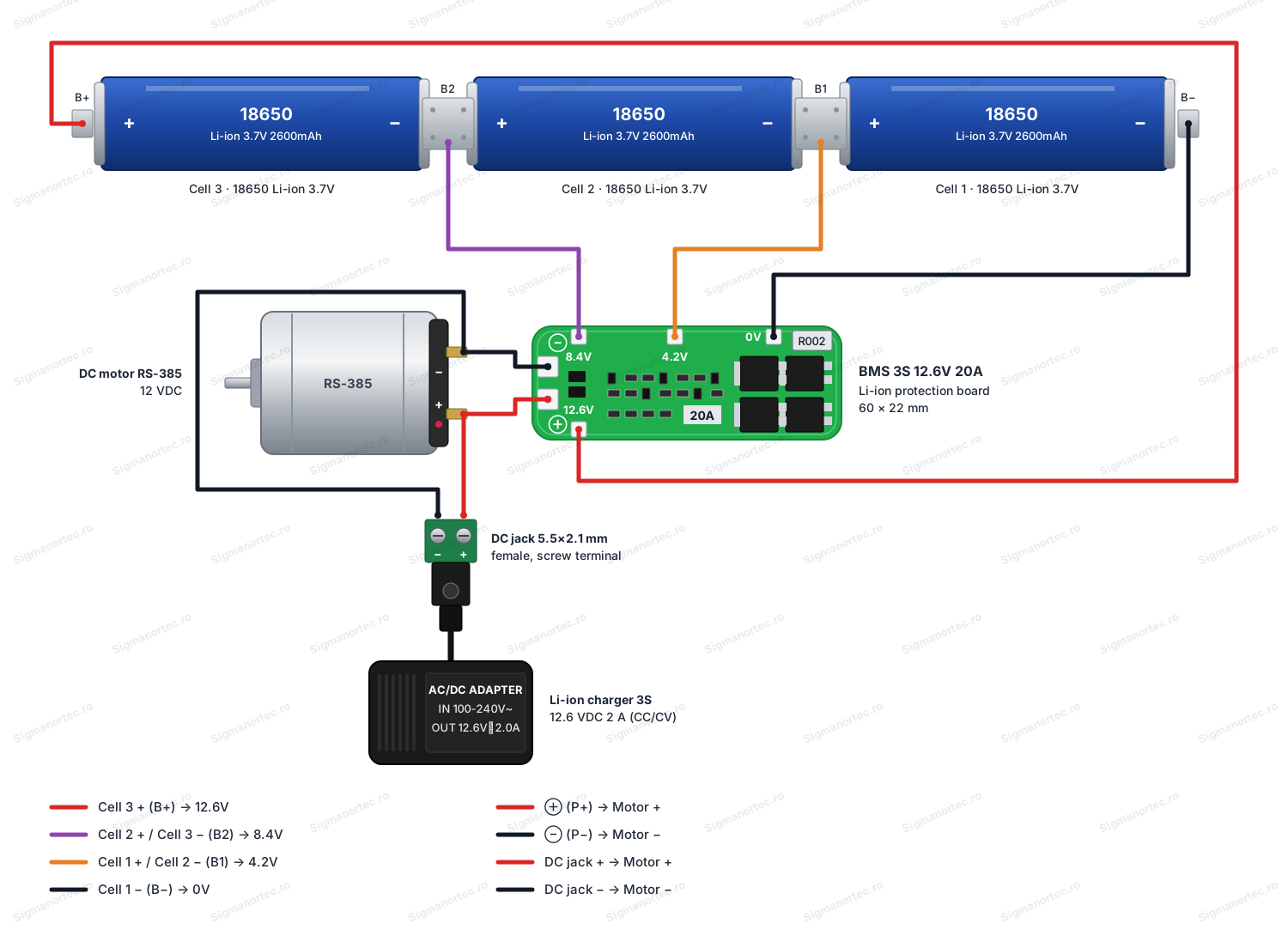
The pack has three 18650 cells connected in series with nickel strips. Connect them to the board as shown in the diagram and in the order given in the table, that is from 0V towards 12.6V. There are no logic levels and no separate power supply. The board is powered directly from the cells, and charging is done with a 3S Li-ion charger with a 12.6 VDC and 2 A output.
| Product pin | Connect to | Function |
|---|---|---|
| 0V | Pack B- (negative of the first cell) | Pack ground and reference for measuring the cells. Connect it first. |
| 4.2V | Pack B1 (connection between cell 1 and cell 2) | Voltage measurement point for the first cell. |
| 8.4V | Pack B2 (connection between cell 2 and cell 3) | Voltage measurement point for the second cell. |
| 12.6V | Pack B+ (positive of cell 3) | Pack positive and voltage measurement point for the third cell. Connect it last. |
| ⊕ (P+) | Positive terminal of the RS-385 motor and positive of the DC 5.5x2.1 mm plug (12.6 VDC 2 A charger) | Output to the load and charging input, positive. |
| ⊖ (P-) | Negative terminal of the RS-385 motor and negative of the DC 5.5x2.1 mm plug | Output to the load and charging input, negative. |
Before soldering, bring the cells to the same voltage, with a difference of at most 0.05 V between them. Use cells of the same type, the same capacity and the same state of charge. After assembling the pack, measure each point against 0V with a multimeter. You should get approximately 3.7 V, 7.4 V and 11.1 V at nominal voltage. If one value differs a lot, check the polarity of the nickel strips before soldering the wires to the board.
Use wires with a cross-section suitable for the load current. For currents close to 20 A, 2.5 mm2 is a reasonable minimum. For the RS-385 motor, which draws approximately 1 - 2 A, thin wires are sufficient.
Power the charger only through the DC plug, at the ⊕ and ⊖ pads. Do not use a simple 12 V supply, because the pack will not charge fully and there is no proper current limiting for Li-ion charging. Check the polarity of the plug with a multimeter before the first connection. In the diagram, the motor and the plug are connected in parallel at the motor terminals. In the final assembly, install a switch on the motor so that it does not run while charging and does not draw part of the charger current.
Configuration:
The board has no buttons, potentiometers, jumpers, switches, LEDs or display. The protection thresholds are fixed, set by the board's circuit, and no setting is saved anywhere. There is nothing to adjust. The configuration consists of choosing the right cells and connecting them correctly. The table below shows how the board behaves in the four possible situations.
| State | Condition | What the board does |
|---|---|---|
| Normal operation | Each cell between the over-discharge threshold and the overcharge threshold, current below 20 A | The ⊕ / ⊖ output is active. The load is powered and the charger can charge the pack. |
| Overcharge | A cell exceeds 4.25 - 4.35 V | Stops charging. Discharging to the load remains possible. |
| Over-discharge | A cell drops below 2.3 - 3.0 V | Stops power to the load to protect the cells. |
| Overcurrent or short circuit | Current above the board limit or a short circuit at the output | Cuts the output. Remove the cause before restarting. |
After a shutdown caused by over-discharge protection or a short circuit, the output usually returns when you connect the charger to the ⊕ and ⊖ pads. After a short circuit, first remove the fault and check the wires and the load.
Usage example:
This example builds a 12 V battery for an RS-385 motor. Take three identical 18650 cells, for example 2500 mAh ones, and measure the voltage of each. If the difference between them exceeds 0.05 V, charge the cell with the lower voltage separately until the values match. Connect the cells in series with nickel strips and measure the total voltage. For charged cells you should read approximately 12.6 V.
Solder the wire from the negative of the pack (B-) to the 0V pad. Then solder B1 to 4.2V and B2 to 8.4V. Solder the last B+ to 12.6V. Measure between 0V and each pad. With charged cells you should get approximately 4.2 V, 8.4 V and 12.6 V. Then measure between ⊕ and ⊖, where you should read approximately 12.6 V.
Connect the motor to ⊕ and ⊖, through the switch you installed. At a draw of approximately 1.5 A, the 2500 mAh cells theoretically give 2.5 Ah / 1.5 A, which is approximately 1.6 hours of operation, in practice a little less. When the voltage of a cell drops below the over-discharge threshold, the motor stops by itself.
To charge, open the motor switch and connect the 12.6 VDC 2 A charger to the plug. At 2 A, the constant current phase theoretically lasts approximately 2.5 Ah / 2 A, which is 1.25 hours. The constant voltage phase at the end extends this, so plan for approximately 1.5 - 2 hours. When the charger indicates full charge, measure at ⊕ and ⊖. The voltage should be close to 12.6 V.
Common problems:
No voltage appears at the output after connection. The cause is usually a cell discharged below the threshold or a wrong connection. Measure each cell and check the order and polarity of the nickel strips. If a cell is discharged below the threshold, connect the charger to ⊕ and ⊖ to restore the output power.
The output shuts off when the motor starts. At start-up, a motor or a drill draws a much higher current than during operation, and the stall current can trigger the overcurrent protection. Use a load with a lower starting current or a soft-start circuit. Disconnect the load and reconnect the charger to restart.
The board gets hot. The load is too high or the board has no ventilation. Reduce the current below 20 A, with a margin if the enclosure is closed, and make sure air circulates around the board.
The pack does not charge fully or stops well below 12.6 V. One of the cells reaches the threshold first, and the board stops charging before the others are full. Measure each cell, balance them separately and always use cells of the same capacity and age.
The voltage measured at the pads is wrong. A wire is soldered to the wrong pad or a cell is installed in reverse. Measure between 0V and each pad and compare with the values of 3.7 V, 7.4 V and 11.1 V at nominal voltage. Correct the connection before connecting the charger.
Limitations and tips:
The board is made for packs of three Li-ion or Li-Po cells of 3.6 - 3.7 V connected in series. Do not use it with other cell counts or with other chemistries, for example LiFePO4, whose voltage thresholds are different. The maximum operating current is 20 A, but at high currents the transistors heat up, so leave a margin and provide ventilation.
The board protects the pack, but it does not replace a fuse. Install a fuse on the positive line, close to the pack, rated for the load. Do not short the ⊕ / ⊖ output while testing. The board does not actively balance the cells, so the initial balancing of the voltages is important.
Each cell in the pack can be doubled with a cell in parallel, as shown in the product photo, for a higher capacity. The pads remain the same, and the maximum current of the board stays 20 A. With this module you can build batteries for tools, LED lamps, small pumps or 12 V backup power supplies. For consumers with a different voltage, add a DC-DC converter after the board output.