

Product images are for informational purposes only and may vary slightly depending on the batch and supplier. Product specifications and prices may be subject to change without notice. We do our best to provide accurate and complete product specifications, but they may not be completely accurate. If you encounter any such situation, please let us know.
The product is intended for specialists and requires qualified and authorized personnel. The product does not include assembly/use instructions . Putting the product into operation by unqualified persons leads to the loss of the warranty according to the Terms and Conditions on the site.
The specified technical parameters (current, power, etc.) represent maximum allowable values under ideal operating conditions. For safe use and optimal lifespan, it is recommended to operate the product continuously at no more than 50% of the specified maximum values.
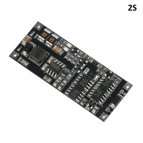
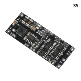
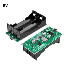
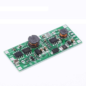
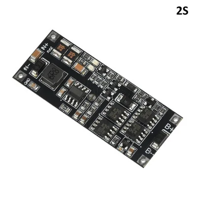
Bidirectional UPS Module, compatible with 2S Lithium, 9–10V
Compact UPS solution for uninterrupted power supply to DC equipment, uses 2S Li-Ion batteries and automatically switches to battery when the source fails. Bidirectional charging and discharging through the same port, current up to 4A continuous, 6A peak, integrated protections against overcharge and overdischarge, LEDs for charging status and load level, ideal for embedded projects and light industrial systems.
Shipping by Thursday 22 October
Buying this product earns you 2.21 RON in loyalty points.

International fast shipping within EU. Free Shipping for orders above 100 EUR in most EU countries.

We ship from our stock within 24H

You earn points with every order, worth 5%.
The compact UPS module is an efficient solution for maintaining continuous power to electrical equipment in the event of a mains voltage failure. The 2S version is designed for Li-Ion batteries with two cells in series (7.4 - 8.4V), with supported capacity between 2 and 15Ah, compatible with 18650, 21700, 26650, 32650 or polymer-type batteries. The module operates on a bidirectional charge-discharge principle with the same port, eliminating the need for complex connections.
The integrated charging chip charges the 2S battery up to 8.2 - 8.4V, with a default charging current of 1.2 - 1.4A. Two LED indicators provide real-time monitoring: the discharge LED lights dimly at loads above 50 - 100mA, becomes brighter above 0.5 - 1A, and reaches maximum brightness above 2A, while the charging LED is on when charging is in progress (IN > BAT by 0.5V), off when charging is complete, and flashes in case of an anomaly. Multiple protections include overcharge, over-discharge, overload, and short circuit through the integrated fuse. The input does not support reverse polarity.
When an external source is connected, the module simultaneously powers the connected equipment and charges the battery. When the input voltage is interrupted, switching to battery power happens automatically. The output voltage is isobaric, equal to the battery voltage in battery mode, with no boost or stabilization, decreasing gradually as the battery discharges. The output path loss in battery mode is approximately 80 milliohms, which means a drop of about 0.1V at 2A. The rated output power is 50W (4A continuous, 6A peak, recommended load under 4A). The module is compatible with equipment that accepts variable DC voltage within the range of the battery used, including projects based on Raspberry Pi, ESP32, Arduino, or other embedded platforms that require stable power and protection against voltage drops.
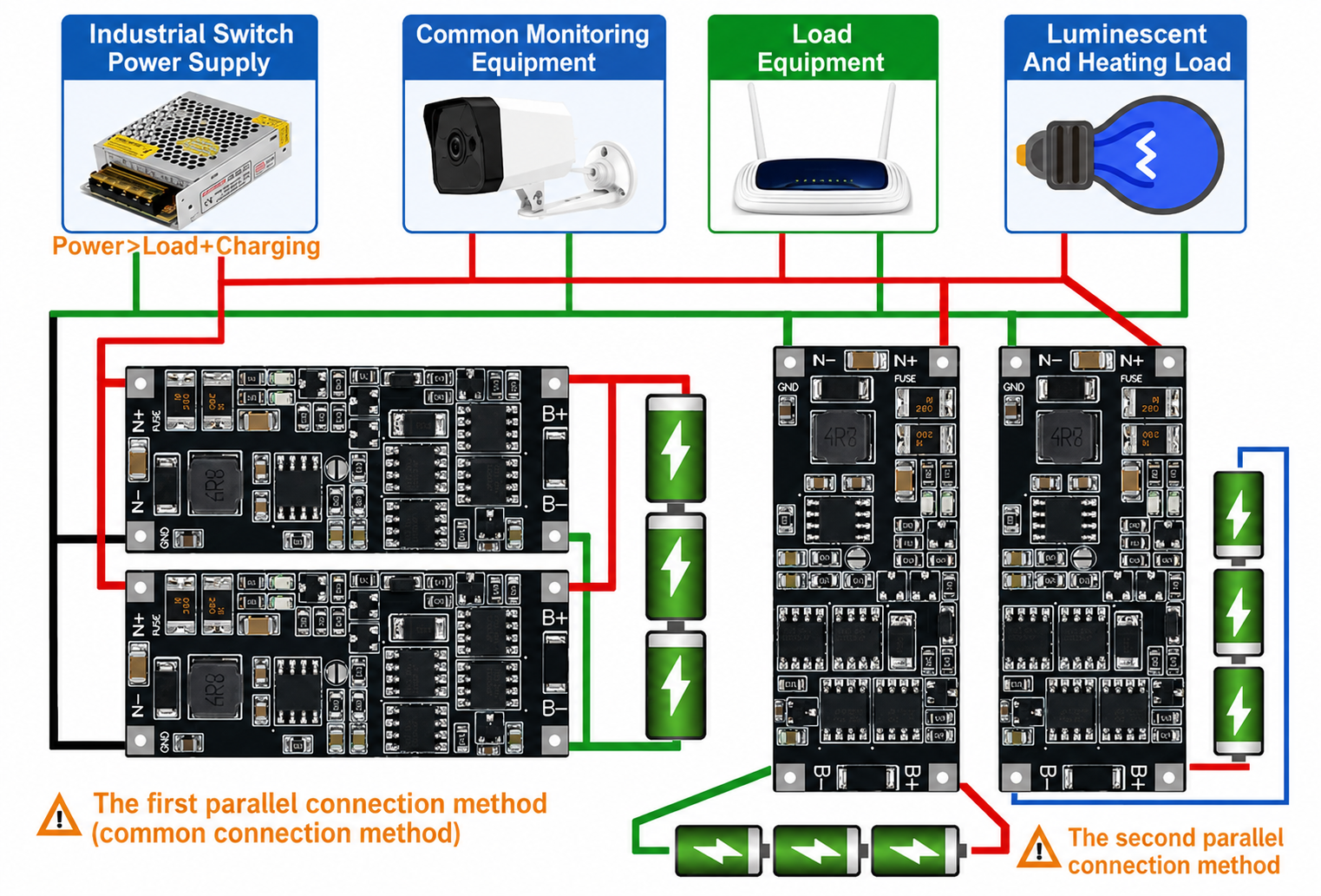
Multiple modules can be connected in parallel to increase available power or for redundancy. There are two methods of parallel connection:
- The first method (common) involves physically stacking the boards one on top of another using copper pins, then connecting the power source and battery. This method is mainly used to stack power, with stacking efficiency of about 80%. For example, two 2S modules connected this way provide a rated current of 4A x 2 x 0.8 = 6.4A, equivalent to about 57W. The recommended limit is a maximum of 3 modules in parallel, with two being sufficient for general use.
- The second method involves connecting the modules in parallel on the power bus, being suitable for increasing runtime and redundancy. If one module or battery fails, the others continue to power the equipment.
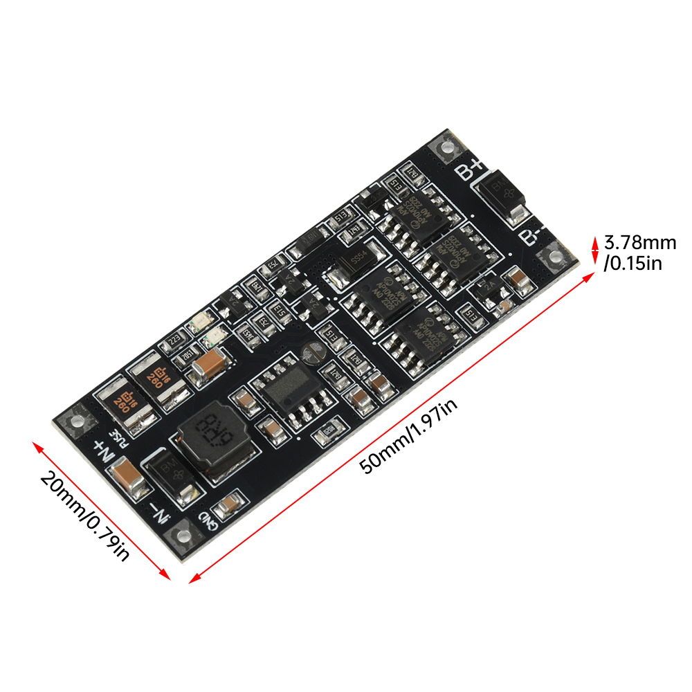
The low weight of 6.20g and compact dimensions of 50 x 20 mm make integration into enclosures or panels easy.
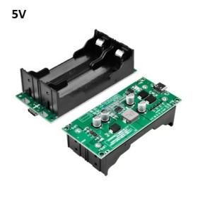
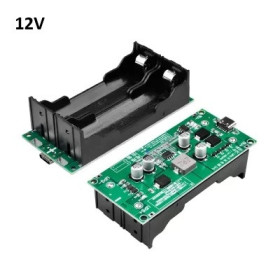
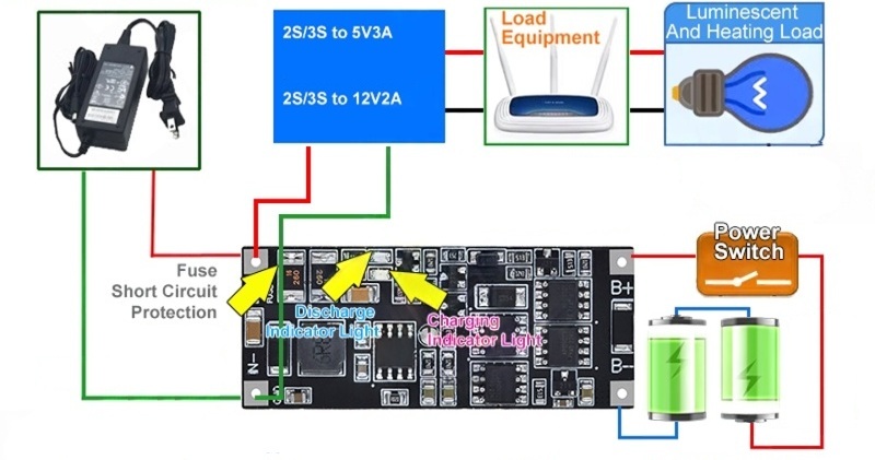
Note: if the powered equipment does not support variable voltage, it is recommended to add a DC-DC module (buck for step-down or boost for step-up) after the output terminals. For example, a 2S/3S-5V/3A buck module for 5V power supply or a 2S/3S-12V/2A boost module for 12V power supply. When connecting motors or electromagnetic loads, it is recommended to connect a capacitor of a few hundred microfarads in parallel across the IN terminals to reduce interference generated by electrical sparks.
Specifications:
Version: 2S (7.4 - 8.4V)
Recommended input voltage: DC 9 - 10V (accepts 9 - 15V)
Maximum input current: 6A
Output voltage: equal to battery voltage (isobaric, unregulated)
2S battery voltage: 7.4 - 8.4V (charging up to 8.2 - 8.4V)
Supported battery capacity: 2 - 15Ah
Compatible battery types: Li-Ion, LiPo, 18650, 21700, 26650, 32650
Output current: 4A continuous, 6A peak (recommended under 4A)
Maximum power: 50W
Default charging current: 1.2 - 1.4A
Protections: Overcharge, over-discharge, overload
Input reverse polarity protection: Not available
Discharge path loss: ~80 milliohms (approx. -0.1V at 2A)
Idle consumption: 0.3 - 0.5mA
Discharge LED indicator: Dimly lit >50mA, bright >0.5A, maximum >2A
Charging LED indicator: On = charging in progress, off = fully charged, flashing = anomaly
Parallel connection: Yes, max 3 modules (2 recommended), efficiency ~80%
UPS switching: Automatic
Dimensions: 50 x 20 mm
Weight: 6.20g
Usage:
Select a 2S Li-Ion battery (7.4 - 8.4V) with a capacity between 2 and 15Ah, of type 18650, 21700, 26650 or polymer. Use of a BMS and balancing board is recommended.
Connect the battery to terminals B+ and B-, strictly observing polarity.
Connect the external power supply (recommended 9 - 10V DC, minimum 6A) to terminals IN+ and IN-. Warning: do not reverse polarity.
Connect the powered equipment to terminals IN+ and IN-, in parallel with the power supply.
Check all connections before applying voltage. Use short cables with sufficient cross-section.
Monitor the charging LED: on = battery is charging, off = fully charged, flashing = anomaly.
Monitor the discharge LED to estimate the load current in real time.
In the event of an external power failure, the module automatically switches to battery power. The output voltage will gradually decrease as the battery discharges.
When the input voltage returns, the module automatically resumes charging the battery.
For parallel connection (method 1 — stacking): physically stack the modules using copper pins, then connect the power supply and battery. Do not exceed 3 modules in parallel.
For parallel connection (method 2 — redundancy): connect the modules independently on the same power bus, each with its own battery. The modules can be placed anywhere in the network.
If the equipment does not support variable voltage, add a DC-DC module after the output terminals to stabilize the voltage.
Usage example:
Dimension diagram:
- Technology
- Lithium Ion
- Number of cells
- 2S
- Input Voltage
- 9-10 V
Produs destinat utilizarii in proiecte electronice, automatizari, prototipare, educatie si cercetare.
Produsul trebuie utilizat numai conform specificatiilor tehnice mentionate in descriere si/sau in documentatia produsului.
Avertismente generale de siguranta:
Nu utilizati produsul la tensiuni, curenti sau temperaturi peste valorile specificate.
Montajul si conectarea trebuie realizate de persoane cu cunostinte tehnice minime in domeniul electric/electronic.
Evitati scurtcircuitele, inversarea polaritatii si conectarea gresita a alimentarii.
Nu lasati produsul alimentat nesupravegheat in timpul testelor.
Produsul nu este jucarie si nu este destinat copiilor.
Pentru modulele electronice, se recomanda utilizarea in carcase, panouri sau montaje protejate, dupa caz.
Identificare produs:
Denumirea produsului, codul/SKU-ul si caracteristicile tehnice sunt mentionate in pagina produsului si/sau pe eticheta ambalajului.
Producator / Importator / Distribuitor:
Sigmanortec S.R.L.
Calea Bucuresti nr. 9, Targu Jiu, Gorj, Romania
E-mail: [email protected]
Website: www.sigmanortec.ro
Persoana responsabila in UE:
Sigmanortec S.R.L.
Calea Bucuresti nr. 9, Targu Jiu, Gorj, Romania
E-mail: [email protected]
Documentatie si siguranta:
Pentru informatii suplimentare, fise tehnice, declaratii de conformitate sau instructiuni, ne puteti contacta la [email protected].
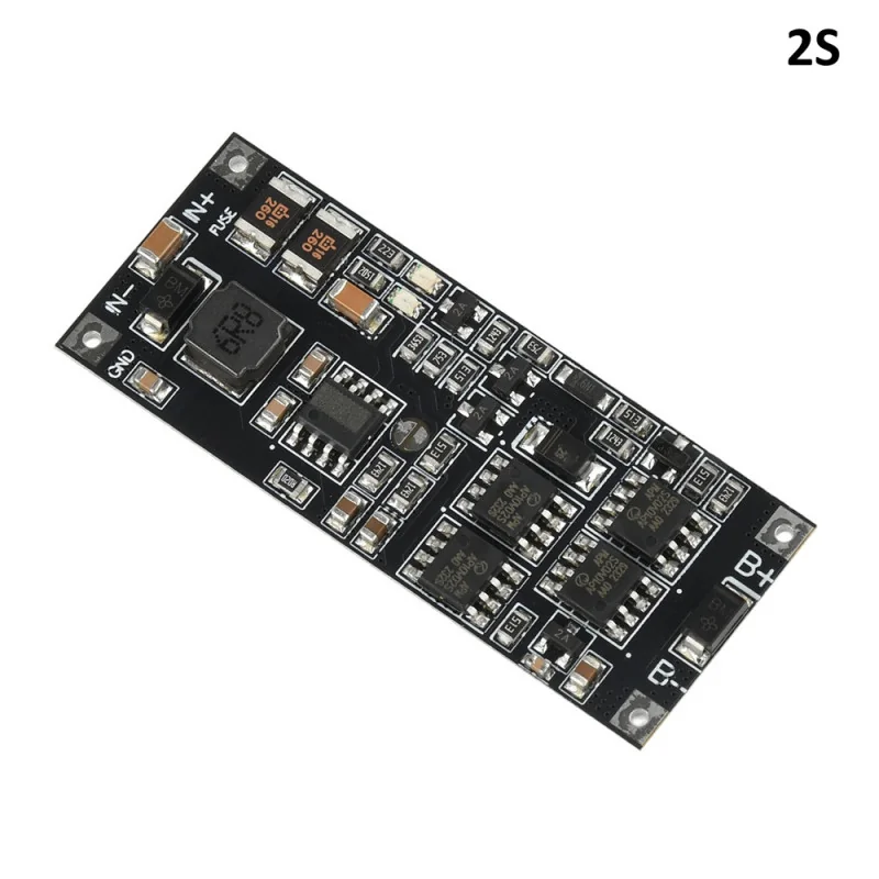
The Bidirectional UPS Module 2S is an uninterruptible power supply board for projects powered by a 2-cell series Li-Ion battery (7.4 - 8.4V). Its role is to take energy from an external 9 - 10V source, power the connected equipment and, at the same time, keep the battery charged, so that if the mains or the source voltage drops, the power supply automatically switches to battery without interruption.
It is useful in projects that cannot afford resets at power loss, routers, surveillance cameras, alarm systems, weather stations, automation consoles with Raspberry Pi or ESP32, where a few seconds of continuous power make the difference until a backup source kicks in or until the mains power comes back.
How it works:
The module uses the same port for charging and discharging, without the need for two separate connectors. When an external voltage is present on IN+ and IN-, the built-in charging chip raises the 2S battery up to 8.2 - 8.4V with a default current of 1.2 - 1.4A, while the same input point also powers the load connected in parallel. If the external voltage disappears, the circuit automatically switches the path so that the battery takes over powering the load, without any manual intervention.
The topology is isobaric, meaning the module does not raise or regulate the output voltage in battery mode, but lets it equal the actual voltage of the battery. In practice, if the battery has 7.8V at that moment, the output will also be 7.8V, and this value gradually decreases as the battery discharges. On the discharge path there is an internal resistance of about 80 milliohms, so at a current of 2A the additional voltage drop is given by the formula I x R, that is 2A x 0.08 ohms, approximately 0.1 - 0.16V.
The two LEDs show the status in real time. The discharge LED lights up weakly above 50 - 100mA, becomes noticeably brighter above 0.5 - 1A and reaches maximum above 2A, thus offering a visual estimate of the current drawn by the load. The charging LED stays lit as long as the input voltage exceeds the battery voltage by at least 0.5V, meaning charging is active, turns off when the battery reaches the 8.2 - 8.4V threshold and blinks when a charging anomaly occurs.
When multiple modules are connected in parallel through the copper pins (stacking), the actual efficiency is about 80 percent of the theoretical sum, due to tolerances between components. For example, two modules connected this way offer a nominal current of 4A x 2 x 0.8, that is approximately 6.4A, equivalent to about 57W, not exactly double a single module.
What you need:
- 1 x Bidirectional UPS Module, Li-Ion 2S compatible, 9-10V
- 1 x 18650 Battery Holder, 2S
- 1 x balancing board for 2S pack
- 1 x 9V Power Supply For Arduino 5.5x2.1
- 1 x set of wires with connectors for power supply
- 1 x Q1 Digital Multimeter, True-RMS, NVC, temperature sensor, automatic
- 1 x Set of 120 electrolytic capacitors, 0.22-470uF
- 1 x ZVS Voltage Booster Module, DC-DC, 45-390V, adjustable
Connection:
The module is not programmed and does not exchange data with a development board, it works independently as a power source, but the powered equipment can be any project with Arduino, ESP32, Raspberry Pi or another platform that accepts the variable voltage of the 2S battery.
Connect the 2S Li-Ion battery, preferably with its own BMS and balancing board, to the B+ and B- terminals of the module, strictly respecting the polarity marked on the board.
Connect the external 9 - 10V source, able to supply at least 6A, to the IN+ and IN- terminals, without reversing the wires, the input has no reverse polarity protection.
Connect the equipment you want to power also to the IN+ and IN- terminals, in parallel with the external source, this is the common charging and output port.
If the powered equipment only works at a fixed voltage, for example 5V or 12V, add a buck or boost DC-DC converter between the module output and the equipment, because the output of this UPS varies with the battery level and is not regulated.
If you are going to power motors or other inductive loads, mount a capacitor of a few hundred microfarads in parallel on the IN terminals to reduce the voltage spikes generated when the load switches.
Common issues:
No LED lights up when the external source is connected, the probable cause is a fully discharged battery below the protection threshold or a wrong connection at B+ and B-, check the battery polarity and voltage with a multimeter before retrying the test.
The charging LED stays on much longer than expected, this generally means the battery has a large capacity relative to the 1.2 - 1.4A charging current, for a 10 - 15Ah battery full charging can take several hours, this is normal.
The charging LED blinks instead of staying on or off, this signals an anomaly, usually an unbalanced cell in the 2S pack or too high a temperature, let the module cool down and check the cell balancing.
The output voltage drops suddenly under load, even if the battery seems charged, the cause is usually an aged battery with high internal resistance or a current demand above 4A continuous, reduce the load or use a battery with higher capacity and discharge current.
When connecting multiple modules in parallel, one of them heats up much more than the others, this usually means the connecting wires between modules do not have the same length and cross-section, which leads to unequal current sharing, use identical and as short as possible wires.
The built-in fuse has blown and the module no longer starts, the cause is almost always a short circuit or a peak current above 6A for a long duration, check the wiring and the load before any other intervention.
Limitations and tips:
The output of this module is not regulated and has no boost or buck function, it closely follows the voltage of the 2S battery, between approximately 6V at full discharge and 8.4V at maximum charge, therefore equipment that needs a fixed voltage must be powered through an additional DC-DC converter.
The recommended continuous current is below 4A, with peaks accepted up to 6A for short durations, and the input has no reverse polarity protection, so a wiring mistake at IN+ and IN- can damage the module or the source.
For projects needing higher power or redundancy, the modules can be placed in parallel through physical stacking, with a maximum of 3 modules recommended, or on the same power bus for fault tolerance, each with its own battery.