



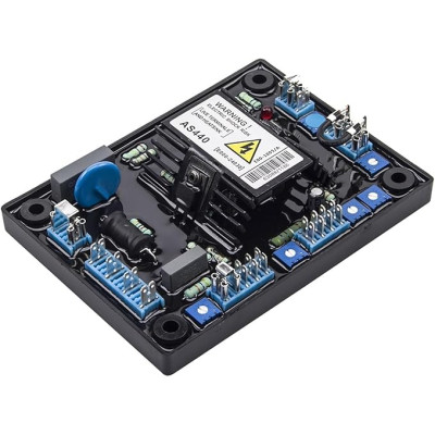


Product images are for informational purposes only and may vary slightly depending on the batch and supplier. Product specifications and prices may be subject to change without notice. We do our best to provide accurate and complete product specifications, but they may not be completely accurate. If you encounter any such situation, please let us know.
The product is intended for specialists and requires qualified and authorized personnel. The product does not include assembly/use instructions . Putting the product into operation by unqualified persons leads to the loss of the warranty according to the Terms and Conditions on the site.
The specified technical parameters (current, power, etc.) represent maximum allowable values under ideal operating conditions. For safe use and optimal lifespan, it is recommended to operate the product continuously at no more than 50% of the specified maximum values.
Automatic Voltage Regulator (AVR) AS440
Automatic voltage regulator for brushless synchronous generators, maintains voltage stability in industrial applications with ±1% accuracy. Compatible with 100-130 VAC or 190-264 VAC sensing at 50/60 Hz, provides excitation up to 82 VDC with 4 A continuous and 7.5 A peak, includes underfrequency and excitation overload protection, and allows external adjustment and droop for parallel operation.
Buying this product earns you 2.64 € in loyalty points.

International fast shipping within EU. Free Shipping for orders above 100 EUR in most EU countries.

We ship from our stock within 24H

You earn points with every order, worth 5%.
The AVR (Automatic Voltage Regulator) module from the AS440 series is designed for automatic output voltage regulation on brushless synchronous generators. The AVR ensures voltage regulation within ±1% and includes under-frequency protection (UFRO) and support for parallel operation.
Specifications:
Sensing (voltage detection): 100–130 VAC or 190–264 VAC, single phase, selectable by jumper, frequency 50/60 Hz
Power supply: 100–264 VAC, single phase, 50/60 Hz
Excitation output: 82 VDC @ 200 VAC, continuous current 4 A (max 7.5 A for 10 s)
Minimum field coil resistance: 15 Ω (10 Ω at input voltage < 175 VAC)
Regulation accuracy: ±1% (with 4% motor adjustment)
External voltage adjustment: 1 kΩ potentiometer, ±10% (increasing resistance decreases the voltage)
Under-frequency protection (UFRO): adjustable, threshold 94–98% of nominal frequency, selectable 50/60 Hz
Excitation overload protection: triggers at 65 VDC, timing 10–15 s
Droop input (parallel operation): 10 Ω, sensitivity 0.07 A for 5% droop
Analog input: ±5 VDC max, input resistance 1 kΩ
Operating temperature: -40 ~ 70°C
Mounting: panel, with screws
Dimensions: 100 x 135 mm
Weight: 250g
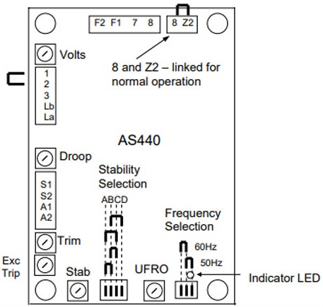
Layout:
| Terminal | Marking | Description |
|---|---|---|
| S1, S2 | SENSING | Voltage input (100–130V / 190–264V) |
| A1, A2 | POWER | Excitation power supply |
| F1, F2 | FIELD | Excitation output to the field coil |
| Z1, Z2 | DROOP | Current transformer input for parallel operation |
| 7, 8, Z2 | LINK | For normal operation, connection between 8 and Z2 |
| TRIM | TRIM | Terminals for external adjustment potentiometer (1 kΩ) |
| STAB Switch | A-B-C-D | Stabilization response selection depending on generator power |
| Potentiometers | — | Adjustments: VOLTS, STABILITY, UFRO, DROOP, VTRIM, EXC TRIP |
Stabilization configuration table
| No. | Power range | Response |
|---|---|---|
| B-D | < 100 kW | Slow |
| A-C | < 100 kW | Fast |
| B-C | 100–550 kW | Fast |
| A-B | > 550 kW | Fast |
Potentiometer table
| Name | Function | Direction |
|---|---|---|
| VOLTS | Generator output voltage adjustment | Clockwise increases output voltage |
| STABILITY | Prevents voltage oscillations | Clockwise increases damping effect |
| STAB SWITCH | Optimizes transient performance | See the table above |
| UFRO | Sets the UFRO inflection point | Clockwise lowers the frequency of the point |
| DROOP | Sets generator droop (up to 5%) | Clockwise increases droop |
| VTRIM | Optimizes analog input sensitivity | Clockwise increases gain/sensitivity |
| EXC TRIP | Sets excitation overcurrent trip threshold | Clockwise increases trip level |
Usage:
Connection: Mount the AVR in the generator panel, away from heat sources. Connect terminals S1 and S2 to the generator output voltage (single phase or between two phases, according to the configuration). Power supply (A1, A2) should be connected to the same source.
Output: Connect terminals F1 and F2 to the rotor field coil (via slip rings or exciter). Observe polarity (F1 positive, F2 negative) for correct operation.
Initial setup: Set the sensing voltage selection jumper (100-130V or 190-264V) and frequency (50/60 Hz). For normal operation, ensure the connection between terminals 8 and Z2 (link). If using an external trimmer, connect it to the TRIM terminals (1 kΩ).
Voltage and stability adjustment: Start the generator at nominal speed. Adjust the VOLTS potentiometer until the voltage reaches the desired value. Adjust STABILITY (by selecting position A-B-C-D according to generator power and then fine-tuning with the potentiometer) until the voltage is stable without oscillations.
Under-frequency protection adjustment (UFRO): Set the UFRO potentiometer to determine the start point of voltage reduction when speed decreases (usually 94-98% of nominal frequency). The correct value ensures that voltage decreases proportionally below nominal speed.
Parallel operation: For generators running in parallel, connect current transformers to terminals Z1 and Z2 and adjust the DROOP potentiometer to achieve 5% droop at zero power factor (0 PF).
Overload protection: If prolonged excitation overload occurs (e.g., short circuit), the EXC TRIP circuit will interrupt after 10-15 seconds. The trip threshold can be adjusted (factory set at 65 VDC).
Attention!
Do not exceed the specified maximum input voltage for sensing and power supply.
Ensure that the field coil resistance is ≥15 Ω (or ≥10 Ω at input voltage below 175 VAC).
If using the analog input, the connected device must be fully galvanically isolated from ground, with an insulation resistance of at least 500 VAC.
If the AVR is mounted in a vertical (portrait) position, the continuous output current must be reduced by 12%.
Produs destinat utilizarii in proiecte electronice, automatizari, prototipare, educatie si cercetare.
Produsul trebuie utilizat numai conform specificatiilor tehnice mentionate in descriere si/sau in documentatia produsului.
Avertismente generale de siguranta:
Nu utilizati produsul la tensiuni, curenti sau temperaturi peste valorile specificate.
Montajul si conectarea trebuie realizate de persoane cu cunostinte tehnice minime in domeniul electric/electronic.
Evitati scurtcircuitele, inversarea polaritatii si conectarea gresita a alimentarii.
Nu lasati produsul alimentat nesupravegheat in timpul testelor.
Produsul nu este jucarie si nu este destinat copiilor.
Pentru modulele electronice, se recomanda utilizarea in carcase, panouri sau montaje protejate, dupa caz.
Identificare produs:
Denumirea produsului, codul/SKU-ul si caracteristicile tehnice sunt mentionate in pagina produsului si/sau pe eticheta ambalajului.
Producator / Importator / Distribuitor:
Sigmanortec S.R.L.
Calea Bucuresti nr. 9, Targu Jiu, Gorj, Romania
E-mail: [email protected]
Website: www.sigmanortec.ro
Persoana responsabila in UE:
Sigmanortec S.R.L.
Calea Bucuresti nr. 9, Targu Jiu, Gorj, Romania
E-mail: [email protected]
Documentatie si siguranta:
Pentru informatii suplimentare, fise tehnice, declaratii de conformitate sau instructiuni, ne puteti contacta la [email protected].